When you create logic circuits using ICs or FPGAs, you can’t easily visualize their operation without special tools. But if you’ve ever seen a mechanical computer (like the Computer History Museum’s Babbage engine) operate, you know you don’t have that problem. Just like it is fascinating to watch a 3D printer or CNC machine, watching mechanical logic gates work can be addictive.
[Anthony] wanted to build some mechanical logic gates and set out designing them using Inkscape. Unlike some common mechanical gate schemes, [Anthony’s] gates use gears to implement the logic operations. He sent the designs off to a laser cutter service and got back parts cut from 3mm acrylic.
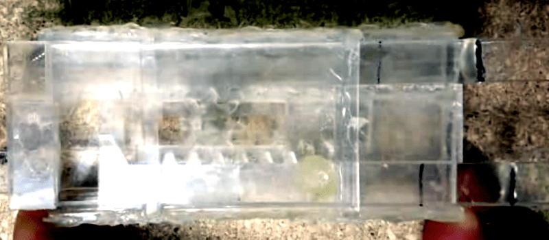
A little adjustment and a lot of hot glue resulted in working gates (see video below). [Anthony’s] site has some good animations showing the operation of each gate type. You can also find downloads of the SVG files for all the components.
We talked about rod logic and its promise for microscopic gates before. If you want to go all out with mechanical computing, you might try your hand at a Turing machine.


It would be great to see a construction which uses several mechanical gatesin order to do something meaningful at the end (counting?/adding?). But there is this friction problem. That could probably only be solved by separate power and data inputs. I wonder how that would look like, implemented mechanically?
i didnt think of that – these will make a functioning computer the same! of course! :)
A mechanical amplifier block is what’s needed. Two counter rotating power shafts with friction clutches that drive the output and are engaged by the difference between the input rod position and output rod position. Slow, easy to make unstable, and prone to wear out but it would work! (a car power-stearing mechanism is a mechanical amplifier as well)
Mechanical Adder: http://woodgears.ca/marbleadd/
Gravity powered.
Posted here on HAD at some point in time I think.
I had to watch the video 3 times before i realized it was a OR gate
Now I want to make mechanical flip-flops!
Would make for a lousy day at the beach, I think. ;-)
Great post! I hope you build a adder!
(an) adder.