It may be better to light a single candle than to curse the darkness, but that was before [RCTestflight] came up with this: a 1000W LED flashlight that outputs about 90,000 lumens of light. That’s a lot: the best pocket LED flashlights output about 700 lumens.
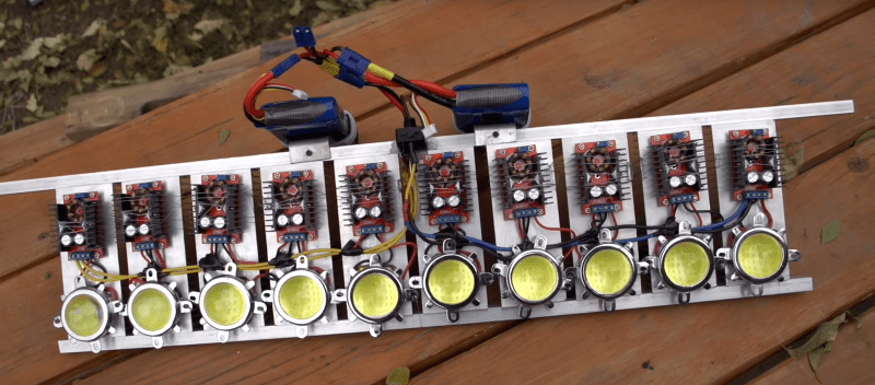
[RCTestflight] built this monstrosity using ten 100-Watt LEDs, running off two RC car batteries. Each of the LEDs is connected to a sizable voltage converter and a very large heatsink that holds all of them in place. He says he gets about 8 minutes of light out of this thing, and that the heatsink gets warm after a minute or two of use. We’re not surprised: LEDs are more efficient than most other devices at converting electrical energy to light, but some always gets lost as heat.
Check out the video after the break. It’s very impressive, but this thing isn’t particularly practical as a handheld. It is big, heavy and is visible for miles. If you really want to light something up it does a great job (for a short period of time) due in part to the inclusion of a glass lens for each of the LEDs. This effectively focuses the beam on a properly distributed area. We wonder what would happen if all the beams were focused on one point? As long as you don’t cross the streams…
We have covered a few more practical builds using similar LEDs, but this thing does have a certain outrageous charm, and could be useful for high-speed video, where the more light, the better.
[Via Popular Mechanics]


What LEDs are these?
Based on the video, I’m guessing something like this http://www.dx.com/p/jr-100w-w-100w-9000lm-6500k-white-light-10-x-10-led-module-30-36v-173825#.VlilLNKrS70
I have the same chips and driver modules, One of these chips have so much power they really are amazing. Video and photo’s do not compare to what it really like being there with the light on.
http://www.survivalindeed.com/the-hybeam
Dead link
Instant daylight.
How long before this is mounted to his car.
No more will people not dip their headlights.
Yup – or you could melt the eyeballs of the drivers of those obnoxious BMW SUVs with their xenon headlights tailgating you on the German Autobahn …
I could use that as a bicycle light. I’d keep it plugged in at home, just point it in the general direction of my destination. (and wear a welding mask on the return trip)
Yeah … I picture you wearing a lab coat and some “evil mad scientist” goggles whilst pedaling a highly modified bike towards this searchlight. People will never make the connection between you and the mysterious light source!
Except for the lab coat. I’m still riding this adrenaline on wheels: http://www.slack.org.uk/photography/hpvwc/hpvwc-0019.html
You sir, owe me a new keyboard and win the internet.
Let the “World’s Brightest LED Flashlight” wars begin!
When too much is not enough… along comes this guy.
That’s hilarious, every time they did the comparison video I would shout, “and then there’s this guy!”
These things are getting more powerful every day…
http://xkcd.com/1603/
Reminder:
The lumen output of LEDs in the datasheet is measured at an internal junction temperature of 25 C which holds true for about 0.1 seconds after you turn them on. The actual lumen output at the actual temperature where they operate is significantly lower, and honest manufacturers give you a de-rating curve for calculating how much you really get.
This is an industry standard that dates back to when LEDs could only output about 20 milliWatts, so they couldn’t heat themselves up enough to matter.
With random China-LEDs you can expect anything between 30-50% drop between actual and specified, both because of the temperature effects, and because of poor quality controls.
For example:
http://s3-blogs.mentor.com/micred/files/2010/12/wpe.jpg
Despite a large heatsink, the thermal interface between the chip and the heatsink presents a bottleneck, and causes the temperature inside to rise significantly when the power is turned on. That’s why LEDs are very sensitive to high ambient temperatures, because even a very large heatsink can’t stop them from overheating.
Usually what happens with LEDs is that the manufacturer specifies the output at something like 1/3 I_max at 25 C junction temperature, which gives a grossly exaggerated estimate for Lm/W and then people who build devices using the LEDs simply take the figure as given and think that the LED will output so-and-so many Watts at full output, when in reality the output can easily be half of that.
This is also why you see LED lightbulbs marketed as “incandecent equivalent” at many times their nominal wattage. Some 7-8 Watt LED bulb can be marketed as a 60 Watt equivalent, when in reality it’s more like a 40 Watt bulb.
That said, if the 90,000 Lumen flashlight is naively built and is actually only 45,000 Lumens, it’s equivalent to about 30 ordinary car headlights.
My experience is that all the LED bulbs I have purchased to replace incandescent bulbs have more than exceeded their 40W or 60W incandescent equivalent rating. Too much so, in fact. I’ve ended up replacing “60W equivalent” LED bulbs with “40W equivalent” LED bulbs, because the 60’s were significantly brighter than the 60W incandescent bulbs I originally had replaced. Enough so to be annoyingly bright.
Might be because the LEDs are directional while the incandecent bulbs aren’t. Your light fixtures matter a great deal as well.
That said, the human eye is pretty shitty at determining absolute brightness. We need about 30% difference between two lightbulbs side-by-side to tell whether one is brighter than the other, and the differences in color temperature don’t help at all.
Or it might also be because the LED is blue-yellow with a poor CRI, which causes you to percieve it to be bright but it actually supresses your color vision and makes objects under the light appear darker.
They might be somewhat directional. But I was also thinking that maybe the color temperature might have something to do with it. The temp is higher on the LED bulbs than the incandescents, even though the LED bulb is marked as “warm white.” I never thought about CRI. I’ve always wanted an excuse to buy a light meter, but I can’t really justify it just to satisfy my curiosity about a few LED bulbs.
“They might be somewhat directional. ”
Haven’t seen an omnidirectional LED yet. Even those light-bulb replicas with “filaments” made out of tiny tiny LED strips are directional in the sense that they’re angled downwards and glow brighter on that side of the strip.
This is so true, I have the same chips and they are really bright for about 1/2 sec then go to normal operating brightness. Also if you buy the chinese chips make sure they light up in rows if you notices a few leds lighting up instead of by row then the chip you have is defective and part of the row structure is working as a resistor.
I’ve been converting old flashlights to led rechargable, but I’d rather build from scratch. where can i source a metal reflector and lens?
Amazon.com, believe it or not. They have a large selection of cheap 100W LEDs, lenses, and other goodies, straight out of China.
thanks for responding but my target design is for a lens 6inches across and about 300lumen with a parabolic reflector and throw of 1/2 km in a spot. i checked amazon and it was just convoy c8 type parts and the 100w leds have an inefficient reflector. It seems that if I want that style of reflector like old incandescent lights had i must get someone with a lathe to build one. the old ever ready 6volt disposable battery types and many more had a large reflector but they were all silvered plastic which is worthless for heatsinking.
you could consider metalizing a 3d print or vacuum formed shape – or maybe bubble-free-formed dome.
heat might limit this approach though. metalized abs is what many flashlights do use though!
They might be somewhat directional. But I was also thinking that maybe the color temperature might have something to do with it. I’ve always wanted an excuse to buy a light meter, but I can’t really justify it just to satisfy my curiosity about a few LED bulbs.
If you want a very powerful flash, have a look at this: http://www.meggaflash.com/
The single-use flash bulbs are still the most powerful solution
This gives the term “light pollution” a whole new twist.
Instead of “rolling coal” it’s rolling sun!
I’m sure this is a naive question, but could he not have used three batteries in series and skipped all the drivers? Or is the driver’s function to limit current?
You are right you can use 3 in series, I find the LED chips only draw what they need.
I believe the driver compensates for voltage drop. Basically supplying constant voltage.
Already done back in 2010 using 15x 100w LEDs.
http://tesladownunder.com/WorldsBrightestBike.htm#Flashlight
15 x 100 =????
LED’s are all fine and dandy – BUT – I always have several “old school” incandescent flashlights/lanterns in the house. Why ? That 3 letter gremlin: “E-M-P”. Which will render all these fancy LED lighting appliances a worthless heap of useless semiconductors and plastic.
It’s actually quite hard to generate an EMP large enough to damage a small device not connected to anything else, especially from a distance. You could scavenge the shielding mesh from a broken microwave oven and fit it to the front of a metal cased flashlight to make it even more EMP proof. You’ll lose a good amount of brightness but still likely end up more efficient than those small incandescent bulbs.
Anything handheld is pretty much impervious to EMP because it works by inducing a current in a conductor, and the smaller the conductor the smaller the current.
It would take a truly ridiculously enormous EMP to destroy something like a walkie-talkie or a cellphone. It would require local electro-magnetic fields on the same order as a lightning strike hitting three feet from you, and if you were close enough to a an energy source that was powerful enough to generate those fields through some sort of explosive energy release like a nuclear bomb or a suitcase explosive EMP weapon, you would be dead anyways.
Besides, in the case of actual EMPs experienced by the public, the air-burst nuclear weapons tested out the Californian coast back in the day, the effect was that the incandecent streetlights blew up due to the induced overcurrent along long stretches of cable.
The EMP effect was due to the fact that the nuclear blast above the atmosphere ionized a very large volume of air, and the shockwave from the blast caused the ionized air to move in ripples. A massive amount of moving electric charge induces a massive low-frequency magnetic pulse which is picked up by long transmission cables.
https://en.wikipedia.org/wiki/Operation_Fishbowl
So exactly how do you put aloe vera on your retinas?
I agree, this needs a large “Do not look into light with remaining eye!” warning sticker.
Looks like Bully Blinders 2.0 if Goonies were still around. One blast and no more bully!
An old 6v “lantern” style light could be used to house a single 100 watt module or simply inspire the design of one. the area where the old 6v lantern battery was housed could contain the lipo cells, voltage converter & whatever else you want to stick in there. A stainless steel pet water dish could take the place of the plastic “reflector” but be more of something to mount the heatsink to. Once you find the led module on amazon, the “often purchased with” part does the reset of the work
I’ve wanted to make a liquid-cooled flashlight using 4 100w leds ever since I saw one guy just playing with one of em. But now I want to one-up this guy… I’m thinking a 4×4 grid of these on a custom waterblock. That would be epic, but I don’t think I can afford to build that right now lol
That would make flashbangs look like cheap, harmless firecrackers :P
http://xkcd.com/1603/
Life imitates art.
Hah Jay..
That’s a good one!
Could these high-power LEDs be pulsed at very short duration – thinking tens of microseconds – for flash photography? Would it be possible to get sharp rise and fall times, especially fall times given that there is a phosphor involved?
Might be better with gas discharge tubes, you can get them in ludicrously huge sizes.
The problem for photography isn’t so much the rise and fall times, but sustaining the flash for n-milliseconds while the shutter is being swept across the frame.
https://en.wikipedia.org/wiki/Flash_synchronization#X
Basically, most modern DSLR cameras use a rolling shutter, and most other cameras use a CMOS sensor that is accessed by the CPU in a sweep that is effectively a rolling shutter, which means that a single fast bright flash isn’t going to expose the whole frame equally. The flash has to turn on right as the sweep starts and sustain output until the whole frame has been scanned or the shutter curtains close.
So the rise and fall times aren’t so essential in this case, instead a constant brightness for however long it takes to sweep the frame is.
For CCD camera sensors, this is different because they dump the entire frame into another CCD chip (a dark frame) before reading it, so they essentially catch the whole frame at once and can use any old bright flash of light as long as it flashes during the time the shutter is open. Unfortunately manufacturers no longer put CCDs in cameras because they’re more expensive.
If the light is bright enough it _will_ penetrate a CCD’s dark frame. With short exposure times and fast moving objects, a ghost image appears.
Taking ‘freeze frame’ pictures is better accomplished with a long exposre time and a very short well timed flash. Of course this requires a dark environment.
That depends on the implementation.
Sometimes the dark frame is just half the sensor masked off with a plastic top. Sometimes it’s a whole other chip set aside from the sensor. Sometimes there is no dark frame, such as in video cameras.
The whole point of the device is that the CCD was developed to be used in analog video systems where each line of the picture can be strobed out like a bucket chain to generate the video signal. When you do that for every line in parallel you can dump the contents of the whole sensor very rapidly.
Problem is it happens faster than your CPUs A/D converter can work – so they put in another identical chip to store the picture in while the CPU works.
Oh, and there’s also an interleaved version where every other line is masked and a microlens array on top guides the light down to the sensing lines. The whole picture can then be strobed down one line to act as an electronic shutter, and then read out from the side.
With a mechanical shutter, a whole frame sensor with no dark frame can be used and it works more or less like film. You open the shutter, flash the light, close the shutter and then spend all the time you want “developing” it. The dark frames are used as a substitute for a proper mechanical shutter in consumer cameras.
I’ve seen similar boost converters around on ebay, amazon,etc, and most of the ones with just one pot are not current limiting. Am I missing how he is controlling the current? Or is it just that the maximum current for those converters at that voltage difference happens to be what those LEDs need?
You can add current limiting to these converter modules with an op-amp, low side current sense resistor, and a few other discretes.
But a lot of the time, it seems the care with which people drive these huge multi-die LEDs equals the care with which the LEDs themselves are constructed. Which isn’t much. Viewed by eye it’s just blinding, but viewed with a camera you’ll see this:
https://i.ytimg.com/vi/b88azSvDROQ/hqdefault.jpg
Simply put, they’re junk. They won’t have a long lifetime, or good lumen maintenance, regardless of whether you drive them properly or not. Unless you drive them far below spec, but then that doesn’t make for an impressive demo. Think of this in the context of having a bit of fun, not an example of how to build a reliable light.