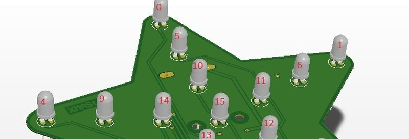
When [hkdcsf] was a teenager, he made a Christmas star with an up counter driving decoder logic and using transistors to light LEDs in festive patterns. He’s revisited this project using modern techniques including a microcontroller, a DC/DC converter, and constant current LED drivers.
The project uses two AA batteries, and that’s what makes the DC/DC converter necessary. Blue LEDs have a forward voltage of just over 3V, and the LED driver chip requires about 0.6V of overhead. Two fresh AAs will run a tad above 3V, but as they discharge, or if he’s using rechargeables, there just won’t be enough potential. To make sure the star works even with whatever LEDs are chosen, the converter takes the nominal 3V from the batteries and converts it to 3.71V.
The microcontroller can operate off of the DC/DC converter voltage or directly from the batteries. The converter is important because the controller disables the DC/DC converter during sleep mode to conserve battery life. The PIC16LF1703 will run down to 1.8V and is miserly on power consumption, especially in sleep mode.
The LED driver takes SPI commands from the PIC and turns the LEDs on. The software on the PIC uses a state machine architecture to drive the animations you can see in the videos below.
The project documentation is impressive and includes a high-level overview of the software and the hardware. There’s also scope captures and information on what drove [hkdcsf’s] design decisions. The star-shaped PCB is a nice touch, too.
Of course, we’ve seen Raspberry Pi trees, and a Christmas tree turned into a binary clock. We were wondering, though, if [hkdcsf] had plans to use the same hardware and software for an LED menorah.


Posted in time to have some constructed for Christmas 2016 if I don’t forget about the project.
:)
Wow, terrific documentation! The firmware block diagrams are great. I haven’t used dedicated LED drivers in the past–definitely something worth looking in to.
Great project!
uC power supply selector (D21 and D22): Does this provide an advantage over just powering the uC directly from the battery?
Great question!
I did not checked it thoroughly, but I think if we power the micro directly from the battery there may be a difference between the micro’s and the LED driver’s logical high-low comparison levels. This may corrupt the SPI communication between them.
However using pull-up resistors and choosing the LED drivers supply voltage considering this too it might be that the two diodes can be omittted and the micro ca be powered directly from the battery as you suggest.
Do not take this to Boston