Take a leap the next time you use SPI and don’t poll for the busy flag. “What, are you crazy? That’s the whole point of the busy flag! It’s a quick check to make sure you don’t kill a byte waiting to be shifted out!” Sure, we thought the same thing, but the other side of the coin is that it takes time to check the busy flag, and that’s time he could be transmitting data. [bigjosh2] calculates that his technique saves 20% of those wasted cycles in this particular case. And he’s “using the force” only because he’s a Jedi master able to rely on the cycle count of a chunk of assembly code.
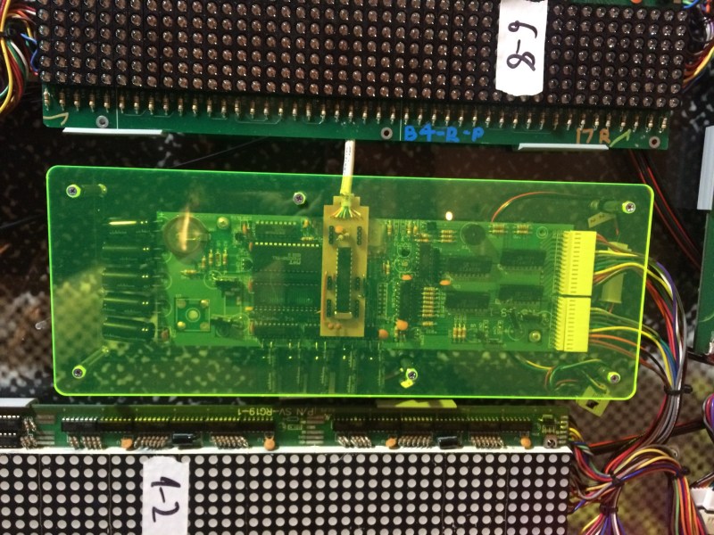
He’s working with an AVR processor, and pumping out bits to drive the vintage LED display pictured above. The ancient chips don’t have buffered SPI so he has to blank the display while shifting new data in to prevent it from glitching. Because the display blank during the SPI transmission, the slower it goes, the dimmer the lights.
He attacks the problem with synchronous code. It takes 2 cycles for the hardware SPI to send each bit, so he twiddles his thumbs (that’s exactly what he wrote in his code comments) for 16 cycles before reloading the SPI register with his next value. This leaves it up to faith in the silicon that the shifting will always take the same number of cycles, but the nice thing about hardware is that it’s deterministic. He ends up killing a few cycles in order to save time by not polling the busy flag.
Still need a crash course in what SPI actually does? [Bil Herd] has you covered with this SPI communication demo.


I mean… I guess if you have to do it that way, that’s cool.
Wrong choice of CPU if you want to run fast SPI. Try an STM32 ARM based board (nucleo dev boards are $10 or less), which can clock SPI upto 100MHz rather than the 8-10MHz available from an AVR.
yes, i learned that the hard way… migrating to STM32 now…
I tried streaming video files from SD-card to FT811. (this was one of the infamous changes in the specs. the first version was only supposed to display a menu and light up some LEDs)
Also, the multiple SPI peripherals are handy! Streaming Data? No problem!
Starting to use ARM was a lot less complicated than i feared it would be.
But Tell me – wich STM32 Parts offer 50Mbps SPI? the fastest i found was around 18…
using STM32F103VG now (another plus point: 96kB RAM, 1MB flash, 32 bit data width… and it still costs the same as Mega128)
Also, AVR seems to lack a “transmit in Progress” bit, it only features a “Transmit complete” bit, wich is kind of … dumb.
now that i am starting with STM32 i am asking myself why i was using AVR in the first place :-)
I mixed clock with SPI speed. The APB2 bus runs at 1/2 the core clock, and SPI on that bus can use a divide by 2 prescaler. The result, at 180MHz core clock is a 45MHz SPI bus (see http://stm32f4-discovery.com/2014/04/library-05-spi-for-stm32f4xx/ )
The STM32F446 supports a 180MHz clock, so a Nucleo-F446RE should do the trick.
I don’t feel like dredging up any of the data sheets. But…
If a TiP bit is “1” during transmission, then wouldn’t the TC bit of the AVR effectively serve the same purpose? If bit is “0”, the transmission is in progress. Unless you don’t know when the SPI is in use due to.. what… multi-threading? On an AVR8??
yes, of course, but then you have the problem discussed in the article, that polling to status bit takes up time. I hoped, that i could just load a byte into SPDR register, and move on with my program. But if you want to receive too, you have to memorize whether the last thing you did was transmitting or receiving (or make shure, that after the last transmit at least 16 clocks have passed).
Maybe there is a simple solution to this (this article just demonstrated one ;-) ), but fact is that i am not really a good programmer, and i never really managed to pick up (inline)-Assembler.
I tend to get things to work, but i’m not shure if its the best solution…
…And my strength definitly isn’t to get that last tenth microsecond out :-)
But things like multiple SPI with FIFO, SDIO etc really simplify things for me. Also, STM32 is native 3.3v, thus i dont need levelshifters anymore (mega128 only makes around 8-10MHz at 3v3, if i remember correctly).
to me, STM32 is now the simpler solution (even though that board is now horribly overengineered…), and now that i am hooked, i think i will stay.
There’s another trick you can pull with SPI on the STM32, it will run in DMA mode. You can point it at a block of buffer RAM and tell it to send that by SPI, no CPU intervention required. It also supports double buffering, so you can build data in second buffer while the first is sending, and have the SPI bus automatically start sending that when it finishes the first block.
Can you set an interrupt on completion of transmission?
yes.
but interrupts take up a lot of time too.
It takes the AVR at leat 2 clocks to jump to the vector, another 2 clocks to jump to the handler, registers have to be saved, then you can do your work, and at last, restore registers. its not really an improvement…
Yes, this is good a technique to squeeze a bit more performance out of AVR SPI. I also used this same technique in my https://hackaday.io/project/6038-pdqgfx-optimzed-avr-lcd-graphics project as one of the optimizations done. However, I had some problems reported that turned out to be caused by using “rjmp .+0” as a delay in the asm. It appears the AVR toolchain can optimize these out in some cases (-mrelax?), so I had to switch to using “adiw r24,0” for a 2-cycle delay.
Saving 20% of the executions an exceedingly inexpensive chuck of codes not a huge saving. A small change to your code and you might introduce errors later on because you’re suddenly stomping on your outgoing bytes because you didn’t check the flag…
The code was too slow — causing the LEDs to be visibly dimmer — and he reduced by 20% the time that the LEDs had to be off. That sounds like a real-life improvement in output, regardless of your abstract judgement that the code is “exceedingly inexpensive”
This is where having hardware FIFOs come in useful. The 24/32-bit (and newer 8-bit, I think) PICs have this in their UARTs. You get to choose to be interrupted when the FIFOs are not full, half-empty or empty, which should make such transfers much more efficient.
Not sure if there’s any similar implementation for SPI though.
Just out of curiosity what is the advantage to this over using the ISR? I get that polling the flag is inefficient, but is ‘twiddling’ thumbs for 16 cycles any better than enabling the interrupt and advancing your SPI task through the ISR?
If I understand correctly, he’s going for ultimate *transmission* speed, here… most ISRs take something like 16 clock-cycles just to jump in and jump out… so the buffer would end up empty for quite a bit of time. Likewise, polling a flag doesn’t take *so many* cycles, but it does take *some*, so even if that poll-loop did nothing *but* check the flag, there’d still be several cycles wasted just processing whether it should loop back and test again, or whether it should jump out of the loop.
A plausibly-interesting aside: Some AVRs’ (more simplistic) serial peripherals require actually toggling a register-bit to do each SPI shift… That system would do well in a case like this.
FYI: The vintage LED display mentioned in the article is on display in the Blue Man Group theater lobby at the Luxor in Vegas. If you’re ever there, go over for a closer look!
Temperature *could* change these timings though, so I’d be careful about using this kind of technique everywhere.
Temperature can change the speed of the system clock, but not the number of cycles that an instruction takes to execute or the speed of the SPI clock relative to the CPU clock. The method will always work unless the temperature is far enough out t make the CPU run unreliably, in which case the traditional method would be in trouble too.
Oh right, I suppose you would be correct there.
When I said that for some reason I was thinking the timing was for the external device, not the internal SPI controller.
This reminds me of an LCD driver I wrote for some Z80 graphing calculators I had. They used busy flags in the toshiba LCDs, but it was more efficient to put in a few NOPs after each data write, and then move on to the next set of data.
Clearing the video buffer was as easy as loading SP as the last address +2 in the buffer, then loading HL as 0x0000, and looping PUSH HL 384 cycles.
I found that I could even drop some of the NOPs, use XOR A to clear the accumulator, then store the accumulator back to the video buffer in the update loop, improving efficiency even further.
Or you could just use a reasonable micro that has DMA and a good feature set, and write some nice async software for it, and the then the problem is solved forever?
And, no, by “nice software”, I don’t mean 7500+ lines of C++ distributed between 18 files of classes, autos, virtuals, and templates upon templates, just to run SPI over DMA.
I am sure this already exists out there, but if someone wrote a “good enough” generic SPI bus gateway task for FreeRTOS, it could really become the standard starting point for so much good stuff …
^ “Not A Hack.”