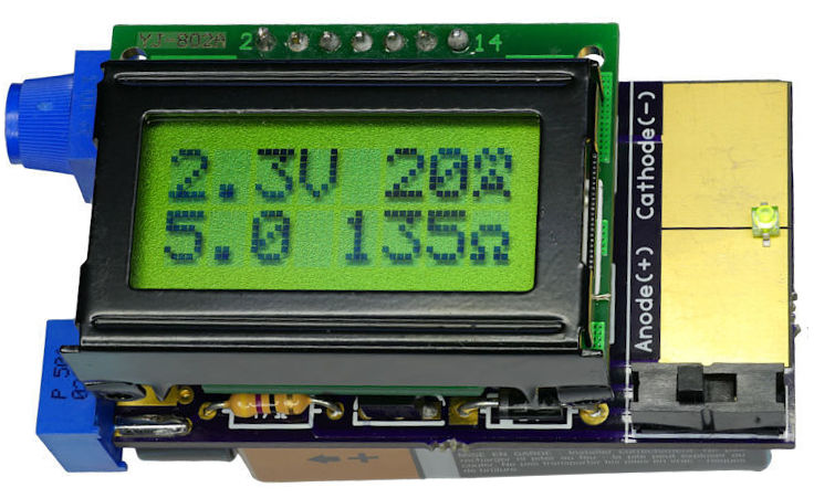
What do you get for the geek who has everything and likes LEDs? A tricked-out LED tester, naturally. [Dave Cook]’s deluxe model sports an LCD screen and two adjustable values: desired current and supply voltage. Dial these in, plug in your LED, and the tiny electronic brain inside figures out the resistor value that you need. How easy is that?
An LED tester can be as easy as a constant-current power supply, and in fact that’s what [Dave]’s first LED tester was, in essence. Set an LM317 circuit up to output 10mA, say, and you can safely test out about any LED. Read off the operating voltage, subtract that from the supply voltage, and then divide by your desired current to figure out the required resistor. It only takes a few seconds, but that’s a few seconds too many!
The new device does the math for you by adding an AVR ATtiny84 into the mix. The microcontroller reads the voltage that the constant current supply requires, does the above-mentioned subtraction and division, and displays the needed resistor. So simple. And as he demonstrates in the video below, it does double-duty as a diode tester.
This is a great beginner’s project, and it introduces a bunch of fundamental ideas: reading the ADC, writing to an LED screen, building a constant current circuit, etc. And at the end, you have a useful tool. This would make a great kit!


The “mA” custom character is really neat!
Oh THAT’s what that is!
That is pretty fantastic. Can’t really be confused for anything else, I’m stealing it.
Sure. Here you go:
0b00001010,
0b00010101,
0b00010001,
0b00000100,
0b00001010,
0b00001110,
0b00010001,
0b00000000
This is a fantastic idea. Perhaps now people can choose a resistor value that has a conformable brightness rather than choosing 20 or 25 mA and having LEDs that burn holes in your retina at 20 meters.
ha! so true!
Nice!
Very cute little device…. but i prefer to do it with the multimeter. I know the current is 0.5mA on the diode tester, and from there I can tell if it is a lazy guy or not.
Would buy that instantly
Me too! Dave, please put this up for sale somewhere!
So would I
I want one!
Thank you for the enthusiasm and compliments!
Well, if enough people are interested, I would be willing to bulk buy the parts and send them out. Or, if someone wants to do that work, I’d be happy to assist with the hex file and PCB order.
I did a quick calculation. In quantity 100, the parts (less battery) cost about $20. The most expensive parts are the PCB, LCD, trimpots, and microcontroller. I’m sure someone who does manufacturing for a living could drive down the costs, but I imagine the quantity would need to be larger.
David,
I might suggest a partial kit of the more difficult parts such as (in order of difficulty as I see it)… Programmed ATtiny, PCB, Display, MCP1702, LM317L, 1N5817 and possibly the variable resistors.
As others have mentioned… you could probably do good with a partial/full kit over on Tindie.
Please let us know if you decide to do any of the above.
Thanks for Sharing
diwght
Thanks for the suggestion. The problem with Tindie is that I’d need to stock product (predict and purchase parts) and then ship over time. The benefit of a Kickstarter for 100 would be one bulk purchase and distribution, without risk of unsold kits. I don’t really want to get into the hardware business. : )
Hmmm. There was someone on the Amp Hour podcast that had a business where they would produce runs of custom products from (largely) stock components. Perhaps a nearly preassembled surface-mount version of the LCD Tester would be more convenient for everyone if the price was comparable.
David
Macrofab
Nice. Second the custom mA character, and very handy for determining the brightness. Also those bare pads are great for smt. All ’round cool.
Oh that is it. Honestly, at first glance I had no idea what is the character.
This nice as a starter project. Selecting one offs. What I would love to see is a led parameter tester. Not only test the forward voltage and current. I bought a lot of white leds cheap off Ebay. Or course these are not prime parts. “Where do you think the less than perfect stuff gets sent?” Leds are funny little devices. They act so differently from part to part, even within the same production batches. What I would love to see. Is a project to track the Lumen, Voltage, Current curves.
Remember all the leds I bought (100 pcs). What I found out about those devices:
1. Not all devices have the same VFWD. At a 20ma CC.
2. Devices with same VFWD, may not have the same Lumen value. Eye eval, no meter.
3. All devices reacted at a different low level VFWD. Excite voltage.
4. Some devices drive hard @3.4V to light, some go crazy @2.4V
See the need to tri-curve test? Lumen meters are not really cheap. Photo resisters are lightband responsive. It would be a true task to hobby a “visible” light red to violet led parameter tester. I am not up to it. Takers?
I have quite the same experience as you have. Concluded that ~10% of the should go to junk. I tested them before using with multimeter or one of those marvelous component testers that shows everything. If that makes it bright enough, it will work with some resistor in series from 3.3 or 5V.
However, after a few premature failures i have come to the conclusion that the $1.x for 100 LEDs is not a good investment if they fail in projects. Ergo, i spend 3-4 from a distributor for 100 leds. In general….. i find components from ebay to be quite a gamble….if you can afford spending time to check them, then you will find 90% are ok. If not, might be worth the extra price through regular channels.
I would think a tester would be too complicated to justify, unless you are a big consumer of LEDs.
Lumen is complicated, but LUX hot that hard or expensive.
Agreed Lumen is a hard value to test. Our QA department would have to test picture tubes, color and BW. BW was easy, color needed special calibrated RGB sensors. This was all to test the parameters of PT’s.
It could be possible to use led’s as light detectors. Even possible use old CCD BW chips, maybe CCD RGB chips too. I have in my mind already ruled out Photon detector/multipliers and photo transistors.
I still say this would be a interesting project if the cost factor came down.
well, difficult and is a relative term. There are plenty of digital sensors that can measure with something like 20% error and maybe putting 100 of them on a sphere is not that big a deal. For hobby, overkill.
But for hobby you are obviously able to use only one in the centre of the beam.
Why not build an integrating sphere instead?
I hope you realize that there is a spread on the parameters for all semiconductors, not just LEDs. LEDs VF is also temperature dependent.
Since the VF varies all over between LEDs the method for control is constant current. The efficacy, or light level output per power input also varies between LEDs. This is why LED vendors bin the parts for you, so that you get parts with roughly the same level of brightness and color.
Controlling the voltage is kind of silly, a constant current driver would provide whatever the minimum bias voltage is for the LED.
Yes, there is a spread. However, i think that most stuff from ebay/whatever is things that normal manufacturers throw out, because they are not on spec. Hence you will find devices with very high or very low Vt, but not some in the middle.
Nice idea. Could you add ‘frequency’ and ‘duty cycle’ parameters so we can check out the brightness of LEDs intended for use in multiplexed displays?
That’s a good idea. Unfortunately, as presently designed, the microcontroller has no control over the LED. The microcontroller only measures the voltages at two points.
Excellent project, very useful tool to have. Since we already have uC for driving LCD next logical step would be to eliminate those pots and use pushbuttons for current and voltage setup via PWM or DAC. Maybe even some easy accessable predefined supply values (3v3, 5v, 9v, 12v). And bigger LCD for displaying power consumed by LED and power required for resistor (that second one is important, you probably don’t want to dissipate 1W on 1/4W resistor). However, this tool already kicks ass, I definitely will make one.
I like the power rating idea. I’ll add that and just have the display toggle on a timer.
I considered using predefined voltages (3.3, 5, 9, 12) but I was concerned that I might leave out a useful voltage.
Looks neat. I wish he would either post the gerbers or sell the PCBs – I like the project well enough, but not enough to spend $50 to get CAD software just to get the PCB layout. Anybody willing to re-lay it out and post the gerbers?
We need a DIY version of this: http://www.instrumentsystems.com/products/led-tester-for-production/
Looks like a scheme to sell his PCB software, Otherwise, why not use something standard like KiCad or Eagle?