Transferring data without error when there is a lot of background noise is a challenge. Dr. Claude E. Shannon in 1948 provided guidance with his theory addressing the capacity of a communications channel in the presence of noise. His work quickly spread beyond communications into other fields. Even other aspects of computer use were impacted. An example is the transfer of data from a storage medium, like a hard drive or CD-ROM. These media and their sensors are not 100% reliable so errors occur. Just as Shannon’s work defines communication channel capacity it defines the transfer rate from a media surface to the read head.
Shannon told us how much could be passed through a channel but didn’t say how. Since 1948 a lot of research effort went into accurately detecting errors and correcting them. Error correction codes (ECC) add extra bits to messages, but their cost pays off in their ability to work around errors. For instance, without ECC the two Voyager spacecraft, now leaving our solar system, would be unable to phone home with the information they’ve gathered because noise would overwhelm their signals. Typically in hardware, like memory, error correction is referred to as ECC. In communications, the term forward error correction (FEC) is used.
Robust communication, or data transfer, is a combination of fancy software and tricky signal processing. I’m going to focus on the software side in this article. You may find some of these techniques useful in communicating data among your devices. While I’ll be using the term communications keep in mind this is applicable to transferring data in general.
Error Handling Issues
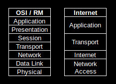 Robust communication requires multiple layers of protocols. Any or all of those layers may have error correction, probably of different types. One layer will address physical transfer of data over wire, fiber, or RF. Another may address message routing and transfer to other systems. The type of error handling and what to do when errors occur is specific to each layer. As a result I can’t provide a definitive statement on what to do when an error is detected as it depends on the protocol’s expectations. To illustrate layers compare the Open Systems Interconnection / Reference Model and the Internet protocol suite.
There are two ways that errors can change bits. A bit can be flipped, i.e. 1 becomes 0 or 0 becomes 1. Or a bit can be erased. An erasure can occur with the RS-232 Standard for interconnecting devices since it defines a 0 as > 3V and a 1 as < -3V. Anything between those is undefined, causing an erasure. Errors can also occur in bursts, taking out multiple bits at once, or on individual bits.
We’re used to thinking in terms of bytes for communications. Generally, communication protocol analysis works with streams of bits when applying mathematical analysis. Fortunately these abstractions can be translated into byte operations for us computer jockeys, but this adds its own complications. 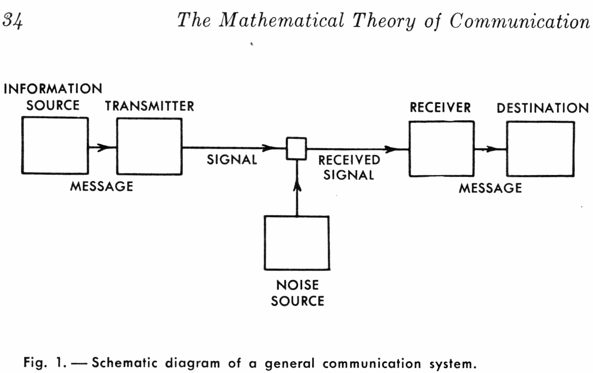 Are the processes little- or big-endian? Is the bit stream processed from the first or last received bit? These don’t change the mathematics but they do change the implementation. We’ll not go into details but be aware of the problems.
Before we get into the details let’s take another look at Shannon’s communications diagram. We’re generating information which is passed to a transmitter where it is encoded. The encoded information passes through a communications channel where noise is introduced. The receiver gathers the encoded data, modified by noise, and decodes it with the goal of error free passage of the information.
Error Detection
Before you can fix an error you have to know that it occurred. A basic error detector is the parity check. You may have encountered parity bits in setting up a serial port where you have to choose even or odd parity. The parity bit is used for error detection. If a bit, data or parity, is changed by the channel the parity check will be wrong and flag an error. A drawback with parity checking is it may not detect multiple bit flips if they offset one another.
Related to parity checking is the checksum. A checksum does an XOR of all the bytes in a message. The checksum is appended to the message. As data arrives the receiver also calculates the checksum and compares it with the received value. If the values do not match the message has errors. As with the parity checking, checksums cannot detect multiple errors that offset one another.
Another use of checksums is verifying the integrity of PROMs in embedded systems. A sad truth of life is that bits will occasionally fail in a PROM, corrupting the program code. The checksum for valid code is written at one end of the PROM’s memory for verification at startup and periodically when running code.
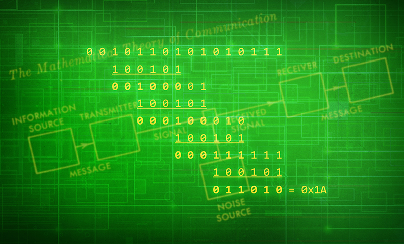
Parity checking and checksums are actually the simplest forms of a cyclic redundancy check (CRC). In mathematical terms, a CRC is the result of a polynomial modulus operation, modulo 2 on the message. You have to see it to realize it’s not complicated. Here’s an example using a message with the bits 0010110101010111 divided by the CRC bit pattern 100101:
0 0 1 0 1 1 0 1 0 1 0 1 0 1 1 1
    1 0 0 1 0 1
    0 0 1 0 0 0 0 1
        1 0 0 1 0 1
        0 0 0 1 0 0 0 1 0
              1 0 0 1 0 1
              0 0 0 1 1 1 1 1 1
                    1 0 0 1 0 1
                    0 1 1 0 1 0 = 0x1A
The values in bold are the result of each step in the process. The CRC for this message is 0x1A. The process starts at the leftmost 1 bit and performs the XOR operation. It shifts right to the next 1 bit and again does the XOR, using additional bits from the message if necessary. This continues until the last bit has been included in a calculation.
Actual implementations of the CRC don’t actually do this division. Most use a lookup table that XORs the table value with the message value. You can find examples in a number of places on the web. If you’re implementing a specific protocol there are probably standard routines available because the CRC bit pattern, actually called the polynomial, is specific to each protocol. The polynomial used by a protocol addresses the types of errors that may occur. Some polynomials handle burst errors better while others handle single bit errors better.
Protocols that rely on CRC, parity, or checksums do not provide error correction and are usually used where noise is not a big problem. A typical use is where data is streamed and a dropped value is not critical because the next copy of it will be along shortly. The other option is where messages can be repeated if an error occurs. These are automatic repeat-request (ARQ) protocols. A message is transmitted to the receiver who sends back a positive acknowledgment (ACK) if no errors are detected, otherwise a negative acknowledgment (NAK) is sent. Because of those abbreviations you may hear them called ACK/NAK codes. If an ACK is received the next message is sent. The current message is repeated if a NAK is sent back.
The drawback with ARQ is the time delay caused by the receiver acknowledging a message and the longer delay caused by repetition when an error occurs. This lead to the development of sliding windows where a number of messages would be sent, for example 7, without break. The receiver would send back an ACK with the sequence number of the last good message. The transmitter would continue by sending the next message after the one that was ACK’d.
Error Correction
The ability to correct an error is critical in obtaining maximum throughput. The introduction of an FEC can be the equivalent of increasing the power of a transmitted signal. It is not uncommon for an FEC to introduce a 3dB gain, which is the same as a doubling of transmission power. (A dB is decibel, a logarithmic scale used to represent power or amplitude ratios.) Decibels are used to determine how close a protocol is to Shannon’s limit.
There are two types of FECs. Convolutional codes work with the bits as they are streamed. Block codes work on entire message chunks. There are a number of both type of codes.
The almost de facto standard for block codes is Reed-Solomon (RS) developed by Irving S. Reed and Gustave Solomon in 1960. You’ll find RS codes in CDs and DVDs, DSL and WiMax, satellite communication, and digital TV. Other block codes are Hamming and Golay.
Reed-Solomon
An RS code works with a message containing data symbols and a set of parity symbols that are appended to the data. The details are specified by {n, k} where n is the message length and k the data length. RS isn’t restricted to operating on bytes as symbols but we’ll just consider 8-bit examples. A common RS code is {255, 223} with 8-bit symbols. This creates a message of 255 bytes with 223 data bytes and 32 parity bytes. With these 32 bytes RS can correct errors in 16 bytes of the message. This means a single bit, or all eight bits, can be wrong in 16 different bytes and the RS will correct them. The number of parity symbols, referred to as 2t, is always twice the number of symbols, just t, that can be corrected.
Convolutional Codes
Convolutional codes work on the bits in a stream. They can be specified with three parameters similar to a block code specification. A {7, 3, 3} code adds 7 bits to the output stream based on 3 bits of input using a memory of 3 bits. Just as with the CRC codes they use a polynomial to encode the input bits to create the output stream.
Short convolutional codes readily lend themselves to hardware encoding. For our {7, 3, 3} code a shift register of 9 bits (for 9 bits times 3 memories) is used. The outputs of the shifts registers pins are wired to a network of XOR gates with the pattern defined by the polynomial.
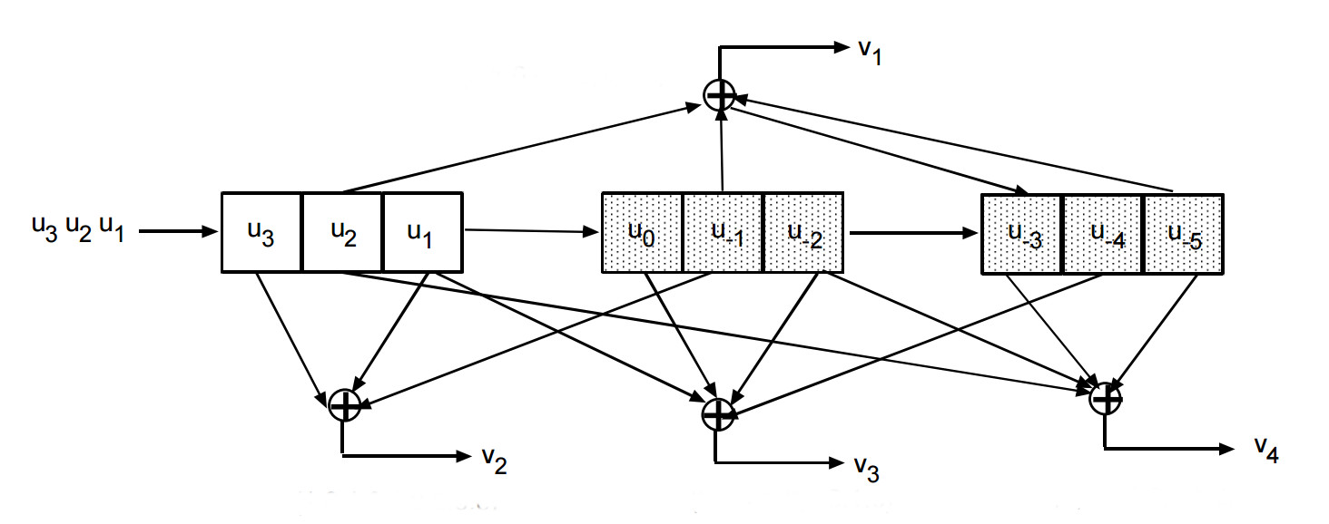
The stream of input bits are shifted into the shift register 3 bits at a time. At each of these shifts the input bits and the XOR gate output bits are put in the output stream at the rate of 7 outputs for every 3 inputs. This type of a code uses memory, the previous 6 bits, in addition to the new 3 input bits to generate the output.
An additional technique is to ‘puncture’ the code. This drops some bits from the output stream to improve the speed of transferring messages. The protocol definition is designed so these bits are readily recovered as part of the FEC. Dropping bits increases the overall throughput.

A convolutional code is a state machine. As such, a graph can be constructed called a trellis diagram. This diagram has time across the top and bit states along the side. It represents the legal bit patterns that can occur in the bit stream at specific times. Software can be used, instead of hardware, to generate the output stream by walking this graph. The decoding of convolutional codes is almost always done in software using trellis codes.
Error correction occurs in decoding because there are only limited legal states available at any node on the graph. When the bit stream contains an illegal code, the decoder knows an error occurred. Assume a decoder that is using 2 input bits from the stream to walk the graph. It encounters a node where only a 00 or a 11 are legal but the input is a 10. The software guesses it should be an 11 and proceeds on that assumption after incrementing an error counter. The process continues making guesses when illegal states are encountered, incrementing the error counter at each guess. When too many errors occur the process backs up to the previous guess and takes the other path. In our example, after tracing back, the decoder would take the path dictated by a 00 input. When the decoder reaches the end of the table this portion of the stream is completely decoded. The decoder starts again at the beginning of the table to process the rest of the stream.
A more sophisticated approach to decoding was developed by Andrew Viterbi, the founder of Qualcomm, which moves through the network along multiple paths. Each path is weighted and at times in the process paths with low weights are discarded.
These approaches are hard decision decoding because the received bits are either 0 or 1. A soft decision decoding approach uses a probability of the bits value. In RS-232 standard a signal above 3V would be a 0 with 100% probability but a signal at 2.5v might be given an 80% probability of being a 0. This probability guides the walk through the network.
Low Density Parity Check
The development of Low Density Parity Checks (LDPC) is interesting. In the 1996, David McKay and Radford M. Neal rediscovered and published a paper about them. Subsequently, it was found that Robert G. Gallager originally discovered and described them in his 1963 PhD thesis. They lay dormant for so many years because the computers in 1963 lacked the power to process them in a reasonable amount of time. LDPC proved superior to the use of convolutional codes layered with RS, approaching near to the Shannon Limit. Development continues on LDPC and they are now being used in communication systems. There is some thought that LDPCs are the fundamental basis for all FECs. RS codes can be shown to be an LDPC, for instance.
Only a few years earlier, a similar FEC, the Turbo Codes were introduced. These codes also came very close to Shannon’s limit. The drawback is they were patented, but the patent expired in 2013.
LDPCs append a series of parity bits to a message. Usually the encoded stream is relatively long — 1024 bits would be a short message. That’s because LDPC is more effective the longer the message.
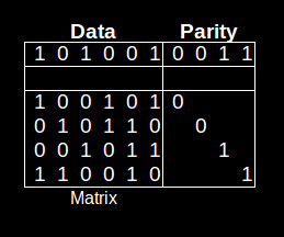
The table shows a tiny message of 6 bits with 4 parity bits. The matrix below the data show the bits used in calculating the parity bits. The calculated bits are appended to the data. As you can see encoding is trivial.
Decoding is much more complex as it involves solving simultaneous equations, one for each line in the matrix. Assume data bit 0, the first data bit, is incorrect. Because bit 0 is incorrect the bits 1, 3, 4, and 5 (lines 1 and 4 equations) may be calculated as incorrect. But the calculation of those bits based on other lines will show they are correct. That means bit 0 must actually be the incorrect bit.
The real complexity in LDPCs is constructing the matrix that determines the parity outputs. This is the focus of research for LDPCs.
FEC Interleaving and Layering
Interleaving and layering are techniques for making FEC even more robust. I’ll discuss them with respect to RS code but they can be used with all FEC codes, including mixing types of FEC code.
Interleaving is simply taking a number of messages and mixing the bytes, in a controlled manner, before they are transmitted. A simple approach with an RS {255, 235} would be to create a set of messages to be interleaved. Send the first symbol from all the messages, than the 2nd symbol, the 3rd, 4th, etc. At the receiving end they are reassigned to their correct message.
Why do this? Assume you have a burst error that wipes out 17 symbols each time it occurs. That would prevent this RS from correcting a message since it can only correct 16 errors. When the messages are de-interleaved the bad bytes are put back in their correct messages. So if all the first symbols were bad they are now correctable when properly positioned in their messages.
The FEC on a CD uses interleaving and layering. A short {32, 28} code is used to correct errors read from the track. Any it cannot correct are marked as erasures and the result is de-interleaved. The result is then processed by a {28, 24} code which fixes any erasures. This works so well it can recover from a loss of 4,000 bits.
Wrap Up
We’ve seen how Shannon building on others work developed the theorem that said we could send a lot more data through a channel than was possible in 1948. This provided the impetus for researchers to develop the error detection and correction codes discussed here. Without FEC the world would be quite different.
Space exploration, especially deep space, absolutely requires communications using FEC. Without FEC increasing the effective signal strength of the miniscule signals from space probes and planetary rovers, like Voyager, Cassini or Curiosity, we’d know little about the other planets and the far reaches of our solar system. The Internet, if it existed at all, would be much slower not only on our personal last mile connections but also on the general internet backbone. The storage devices in our computers would be slower since they use FEC to recover errors in reading drives.
There is one more important element that has not been addressed, the electrical or RF signals used for data transmission. I may get to them in a future article.


Think you could add a read more button so that you don’t need to scroll for hours on the front page to get to other posts?
Also, add buttons for printable version or download pdf version would by nice.
Huh? Why would one want such separate buttons when CSS can handle the printable version easily when you just press print in your browser. And as for pdf.. just print to pdf?
I don’t understand the complaint – middle click and open each article to its own tab before reading them.
“the bolded values”. The word is “enbigened”.
Only on the Simpsons.
Nice explanation.
Fantastic writeup.
Defiantly takes me back, between just RS232 modem protocol CRC stuff into later the OSI transport, network, and data link coding for network communications, and having to interface with new network hardware that had no software to go with it. This is OLD school, except back then you really couldn’t be taught this stuff so much as having to learn it on the job the hard way, especially since the internet wasn’t around – thus, it was much more difficult to get standards for these things. While the theory is interesting, obviously the real stuff was much more fun.
I am LOVING the latest trend in articles. Keep it up!!
Cool article.
But I’m confused… should the 3rd parity bit in the LDPC table be a 0?
Sharp attention to detail, timrc. I’ll make a note in the caption for the image.
I am currently working on reverse engineering the serial communications between the microcontroller and the balancing chips in the Nissan Leaf battery pack Battery Management System (BMS)… I need to reconfigure the battery pack, and BMS for use in my Solectria E10 (Electric Truck).
They used a non-standard CRC8, polynomial 0x85.
These are the steps I used to reverse engineer the CRC.
http://youtu.be/g8ydgU9fdx4
Thanks for watching,
Wolf
“A checksum does an XOR of all the bytes in a message. The checksum is appended to the message. As data arrives the receiver also calculates the checksum and compares it with the received value. If the values do not match the message has errors.”
This is incorrect. You are thinking of a CRC. CRCs use XORs and are typically verified in the manor you suggest. A checksum is literally that, a sum. It’s an addition of all the bytes in a message including a checksum byte or word which is intended to make the sum total zero (considering roll-overs). If the final checksum of the message, including the checksum value (byte or word), is equal to zero, the message is (likely) good.
I recently discovered at new (well, to me) way to verify a CRC. Say you have some hex data – e.g. DEADBEEF The CRC16 of that is 0xE59B. The CRC of the original message, with the CRC appended (low byte first) is 0x0000.
This makes life easy for me when verifying CRCs in FPGAs hardware. Rather than buffering data and comparing, you just check that the CRC is zero at the end of the message.
CRC16(DEADBEEF9BE5) => 0x0000
This also allows you to do some ugly things – if data is verified using CRCs, and has lots of zeros you can insert anything you like, just as long as the inserted data has the CRC tacked on the end.
CRC16(12340000000000000000) => 0x9EC6
CRC16(123400DEADBEEF9BE500) => 0x9EC6
And as CRCs built around XORs, you can extend this technique to do whatever you want with the data. Want to patch a CRC-verified binary? Sure you can do that, just find somewhere harmless further in the file in to balance out the ‘corruption’.
The upshot is CRCs only protect against random errors – not deliberate errors. Don’t trust em!
XOR is a sum over GF(2). The article’s incorrect in suggesting that an XOR is the only way to compute a checksum, though.
QR codes use Reed-Solomon and a few other things including the way they layout the data and the EC bits. There are four levels of possible EC, including one that you can zap more than half the bits (why you can put a picture in the middle).
They actually use a related code called BCH, similar to most MLC SSDs.
BCH(64,56) and BCH(32,24) is also used on HDMI for protecting the non-video data packets (e.g. Audio)
Just to see if I understand correctly (since I don’t find it that trivial), in the LPDC example, the parity is calculated by ORing or ANDing the matrix rows with the data?
It is an AND vertically and an XOR horizontally.
It’s a bit expensive, but one of the best books you can buy on this subject is “Error Control Coding” by Shu Lin. It even includes step by step implementation for most algorithms that makes it easy to write your own implementations.
http://amzn.to/1osXuD4
Hamming Codes for idiots like me: http://datagenetics.com/blog/january42016/index.html
anyone knows a similar tutorial for LDPC? I totally dont get this matrix
Thanks, great article. Would welcome more like this.
Great article, again Rud.
I’m afraid I have to share my favourite geek joke now, though.
What’s this:
“Pieces of seven, squark. Pieces of seven”?
A parroty error.
A fascinating development in this area is rateless codes, such as fountain codes. These are probabilistic codes that let a sender broadcast an endless stream of blocks; any receiver can listen in and be able to decode the original message after accumulating enough valid blocks, regardless of when they started listening and which blocks they missed!
One of the more interesting facets to fountain codes is they can dynamically adjust their information to parity ratio to accommodate different channel characteristics. If it’s a noisy channel scale the parity up to enable receivers to reconstruct the data, if it’s a quiet channel scale it back so throughput gets closer to Shannon’s number.
I think you must be thinking of a different code – the whole point of the fountain code is that you don’t have to know the error rate of your receivers, or adjust for them.
What if when using a RS code (i.e 255,223) an error occurs on just one of the 32 parity (data) Bytes? I suppose that all the frame is lost, is it true?
If anyone is still confused, a great explanation of above topics can be found in Andrew S. Tanenbaum book “Computer networks” 5ed, pages 202-215.
Such a great explanation. You can read a thesis about LDCP here (in Spanish) https://inaoe.repositorioinstitucional.mx/jspui/bitstream/1009/224/1/CastañedaBWG.pdf
Do you think that nowadays microcontrollers like ESP32 can do LDCP encoding and decoding?