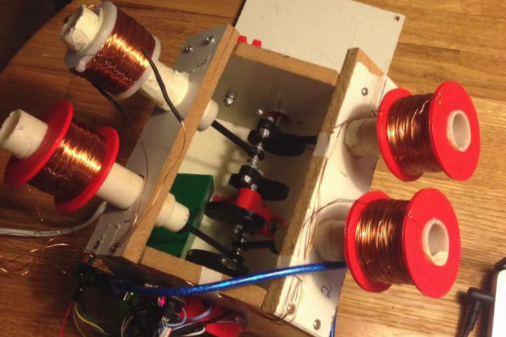
Want to really understand how something works? Make one yourself. That’s the approach that Reddit user [Oskarbjo] took with this neat electric motor build. He made the whole thing from scratch, using an Arduino, 3D printing, and ample quantities of wire to create a solenoid motor. This transforms the linear force of a solenoid, where a magnet is moved by a magnetic field, into rotary force. It’s rather like an internal combustion engine, but driven by electricity instead of explosions. Hopefully.
[Oskarbjo]’s engine seems to work, including a rather neat mechanism to detect the rotation of the shaft and relay that back to the controller. He hasn’t posted much detail in the build process, unfortunately, but did say that “If you’d want to build something similar I can probably help you out a bit, but half the fun is coming up with your own solutions.” Amen to that. We’ve seen a few neat solenoid motor builds, but this one wins points for starting from scratch. There is an Instagram video of the motor running after the break.


Does anybody have any thoughts regarding powering a vehicle with a version of this? Not as efficient as just using an electric motor, sure. But it’s an interesting hybrid of an engine and a motor. I even read a hair-brained comment years ago from someone who wanted to make drop-in cylinder sized solenoids that would convert an engine into a motor using the existing crankshaft and drivetrain. I’m curious what sort of power levels V8 made of solenoids could achieve.
I don’t know why you’d ever do it, outside of the novelty factor. Solenoid motors are inferior to every type of rotating motor in every way. Less efficient, more vibration, more wearing parts…
Well, less efficient, but there is no reason it would have more vibration or more wearing parts. The counterweight on the crankshaft could be adjusted accordingly to reduce vibration, and / or a flat arrangement could be used for the cylinders.
There is still high order flexing vibration, and vibration and noise from the piston movement. And there are many more moving parts as well as sliding interfaces, so there is more wear. Also efficiency is like 50% compared to 95%+.
I agree with the efficiency, the rest is no different than a normal engine, except the solenoid engine runs at lower temperature.
The noise and vibration won’t be any more than in an internal combustion engine.
The “less efficient” aspect kills it regardless. The power-to-weight ratio is pathetic compared to rotaries and ultimately that renders it useless.
But standard rotary electric motors don’t sound as cool as pistons (solenoids in this case) flying around at 14,000+ RPM.
It would be an interesting project just for fun. I guess there are different ways to do it, all with good and bad points-
1) Voice coil style solenoids, where the electromagnets move and the magnets are stationary.
2) “ferrous plunger” style solenoid where the moving part is a piece of ferrous metal that is pulled into the electromagnet by the field. This could be spring loaded or not.
3) Magnetic plunger style solenoids where the moving part is a permanent magnet and the electromagnet is embedded in the cylinder wall. These present design issues as eddy currents can be induced in solid metal cylinder walls, so careful design is needed of the coil form. The advantage to this setup is built in regenerative braking / power generation during deceleration.
4) Electro-hydraulic solenoids were the moving part is a ferro-fluid. This fluid then pushes a conventional hydraulic (non-ferrous) piston. These are slow, but can provide tremendous torque.
“after the break.” – what break? are there Ads? or is this some sort of “journalizt [sic]” speak? How about saying “below”, or “in the video below”.
Is it just me that gets irritated by this? This is probably the hundredth time I’ve seen it here on Hackaday, so I have been patient.
Yeah its just you. HaD has the most toxic and rude web community I’ve ever frequented. You guys pick at things like scabs, nitpicking every minute and pointless issue
If what is said is not what is meant then, what ought to be done remains undone.
No one forces you to read the comments of this or any webpage.
Once it gets bumped from the main page to the blog page the you will have to enter the page specific to this article. It’s a way to let people know that there’s a video to watch should they want to do so.
Complaining about ‘after the break’ is old hat. Everyone else has reverted back to commenting about proofreading, grammar, and spelling.
line breaks are often used to separate different areas on a page, so it is on the point and relevant.
Do people use the “main page”? You can only see a fraction of the articles there, in a terrible condensed format.
“the break” in a blog post is the point where the article gets folded into a summary part and extended part.
If this irritates you, I suggest retreating to a darkened room with no internet and contemplate the true meaning of life.
The people here are quite rude and irascible, I put that down to a high ASD factor among hacker types.
ASD= Allowable Stress Design??? is this or some kind of joke…believe me…Itry to understand english,thanks
I’m guessing ASD=Autism Spectrum Disorder in this case.
It just means that if you’re reading it on the front page or the blog, it won’t load. When you click through to the article, you’ll see it.
“after the break” refers to the “read more” link on the home page. “below” makes no sense if the video is not below the text, because the video doesn’t show up on the home page.
Rotary motor based on this (think Wankel engine) might work. Now that would indeed be 3d printable, just use a bismuth alloy such as BiISn (mp around 60c)doped with a small amount of manganese to boost the magnetic properties.
Or for that matter MnO2, it does not matter as long as the core(s) interact magnetically. Powdered iron mixed with polymorph would also work, or hotmelt glue, or.. you get the idea.
Similar, sort of
https://www.youtube.com/watch?v=OZWeNPi2XkE
I can see that being quite a popular system in the next decade. (if we keep using petrol, diesel and gases)
Cancer?
I concur. Being able to electronically drive the intake/exhaust can result in extremely good efficiency. Plus KvK has plans to turn the system into an air compressor when engine braking to store air that can later be directly driven back into the chamber for boost.
The Freevalve system can be used for high rev motorcycle engines and likewise large vehicles with low rpm.
This is in my opinion the greatest upgrade to the IC engine since turbos in the late 70’s.
If you move the analogy back to the ICE it becomes apparent that the bouncing up and down and all those cam springs makes for a really inefficient engine. Wankels have a high red line, but the true rotary designs really rev it up. Chrysler had a prototype, Parnelli Jones raced in front in the 1967 Indy 500 till a fuel pump drive gave out just 3 laps to go. Gas turbine! Closest to the electric motor as we seem to get. They revolutionized the marine world at the end of the 1800’s.
Chrysler did not make the Indy turbine. Pratt & Whitney did. And it was a transmission bearing, not the fuel pump.
https://en.wikipedia.org/wiki/STP-Paxton_Turbocar