One of the easiest ways to make PC boards at home is to use the toner transfer method. The idea is simple: print the artwork using a laser printer and then use a clothes iron to transfer the toner from the paper to a clean copper clad board. The toner is essentially plastic, so it will melt and stick to the board, and it will also resist etchant.
There are several things you can do to make things easier. The first is the choice of paper. However, the other highly variable part of the process is the clothes iron. You have to arrange for the right amount of heat and pressure. If you don’t do a lot of boards, you’ll probably have to make several passes at getting this right, scrubbing the reject boards with acetone and scouring pads to clean them again.
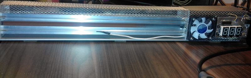
[Igor] had enough of the clothes iron and knew that other people have used lamination machines to get the toner off the paper and on the blank board. He started with a commercial laminator but hacked it for PID control of the temperature and made other improvements.
The laminator now sports an ATmega8, a type-K thermocouple (with an IC to read it), and an LED display. The finished product looks great and–we hope–gives [Igor] better PCBs. If you haven’t seen the laminator method for doing toner transfer before, you can watch the video below (but note, that’s not [Igor’s] laminator).
We’ve covered upgrading laminators before. Before you hack up a laminator, though, you might consider trying the heatless transfer method we covered a few weeks ago.


Cloths irons for applying heat in any other application other than the one they were designed for is always fraught with problems mostly because the thermostats on them are calibrated in fabric types.
when using an iron for toner transfer, it’s usually on “Burn all of the clothes” setting
Mix ingredients in large mixing bowl. Preheat oven to “Cotton” for 15 minutes. bake until brown on top.
I’ve been using a laminator for this purpose for years. However , skip the toner transfer method and go straight to dry film resist. Its cheap, easy to apply with a laminator, and provides much better , board-house quality copper. I have never understood the popularity of the toner transfer method with the photographic process being just as easy, producing much better results.
Cost and availability.
Because it has 2 additional steps that require extra equipment, chemical(s) and “dialing in”…Also it requires you to print onto transparencies, which I personally found to be a problem (pitting that ends up being transfered to the board itself), need a different brand of toner…
Personally I think I’ll keep pursuing the possibility of DIY converting a cheapo-chinese CO2 laser to Nd:YAG from ebay junk and just ablate the copper off directly :D
I bet if you could find a used t shirt screen printing press, that would probably work really good.
That’d be a good option for labeling multiple boards.
One nude thing about the toner transfer method is it can be repeated after etching to apply labels.
a silkscreen press is little more than a piece of light fabric in a frame, hence ‘silk screen’
I believe he meant a t shirt heat press used for applying screen printed transfers to garments.
It is a great deal more than just that and silkscreening is a far more difficult art than most realize.
I’m thinking Kratz means a t shirt dye-sublimation press. I’ve thought about this before, they’re generally timer and temperature controlled with variable clamping pressure.
Oh cool, I have the same model of laminator that he has.
Did you modified it too?
Haven’t. I don’t do a lot of home PCB fabrication, but I might if I find the need for it.
I tried to mod one of those and burnt the rollers during code development and it ended there. I bought another laminator that worked out of the box but still isn’t ideal because of the motor speed (it needs to be slower) so I have to put the PCB through several times and that reduces the resolution a bit because of the toner smearing a little. But it’s not too bad, I can still do 5mill traces and 0.5mm QFP etc with no solder mask. Probably also 0.4mm QFP as well but I haven’t tried that yet.
I am using –
http://www.pcbfx.com/main_site/pages/products/transfer_paper.html
and –
http://www.pcbfx.com/main_site/pages/products/toner_foils.html
to get the results above.
The problem is that the motors in cheap laminators are high (mains) voltage synchronous so I is very hard to slow them down.
One hacker solved that problem this way –
https://hackaday.io/project/3363-apache-al13p-laminator-one-pass-pcb-toner-xfer
I used a laminator very similar to the one linked immediately above. I gave up with the smaller one because the thermal mass of the smaller rollers is far less than the larger ones and a bit of just plain frustration after burning the rollers but you may get better mileage.
I have also considered a chemical toner fusing here –
http://www.instructables.com/id/Heatless-cold-Toner-Transfer-for-PCB-Making/
So it isn’t hard to get good results using this method and it’s quite quick to do but I haven’t solved the double sided registration problem. I am hoping that using a right angle square as a guide will allow me to do the double sided thing with chemical toner transfer.
Hey,
How many iterations did you make? This was the first use of my laminator, and I put PCB 4+10 times, and it looks quite ok: http://morethanuser.blogspot.com/2016/03/esp12e-oled-wireless-notifier.html For smaller PCB (2x4cm) it needs to take about 10 iterations.
Regards,
Igor.
I have a laminator with roller that are twice the diameter and I pass the PCB through probably 6 to 10 times depending on the size of the PCB. This is probably more than is necessary but slight smudging of the traces is better than the toner falling off.
The main factors are temperature regulation, roller speed and thermal mass. If you have rollers too fast then it needs more times through because you need ‘x’ amount of heat. If the rollers are too small then temperature regulation needs to be even better. You can compensate for these things by increasing the temp but then you get smudging.
Old fusor roller out of a laser printer works well too. And built for this sort of application. :)
I saw what you did there!
I did much the same with much the same lol.
I used a laminator that looks identical (at least from the outside) and it is sold in Australia as a “Lowell LOOL280”.
First up – different toners have different melting points. The toner I was using had a higher that average melting point. Some people have been using the same model without modification and with good results – I assume they have low melting point toner.
I replaced the thermostat just like other hackers that were successful but it didn’t work for me. Only partial toner transfer.
Then I made a full blown controller with a ATmega328p, opto isolated high voltage switching for the heaters and motor, high voltage zero crossing detector for the micro, 16×2 LCD Display and controls and I used a diode and op-amp for a temperature sensor because I didn’t have anything else lying around.
When writing the code – I accidentally left the heaters coded “Full On” when testing and burnt the rollers. I gave up with the cheep laminator at this point. The project is here – https://hackaday.io/project/4519-toner-transfer-fuser-from-cheap-laminator
I then bought a lager and more expensive unit that was variable up to 200 degrees Celsius. It was an even cheeper version like this one here – https://hackaday.io/project/3363-apache-al13p-laminator-one-pass-pcb-toner-xfer
The new larger / hotter laminator only gave marginally better result – still not at all usable.
Then I bought another laser printer and *BINGO* – fairly good results every time. I still use this laminator *without modification*.
So – here is what I learnt and somethings that are not obvious.
A lot of people say that the quality of the Toner Transfer Method are poor but the results can be very good – here is what are the hurdles.
The biggest influence on how much you need to do to get this to work *well* is the toner! High melting point toner well never give good or even acceptable results with an un-moddified laminator. Low melting point toner will give *fair* results on an un-modified laminator for small thin circuit boards down to about 10mill traces and anything below that gets wonky.
Your enemies are –
Thin rollers – they have a low thermal mass and you can’t correct for this with PID.
Compounding the above problem is synchronous motors.
You can’t use PID to compensate for low thermal mass rollers at the fixed speed of the synchronous motor because the heater is on one side of the roller and the PCB is on the other and there is too much time between the two.
I pass the PCB through several times (6 or so) and that helps but each pass smears the traces a little more and this means that you can’t do lower than 5 – 7 mill traces.
The solution is larger rollers and a non-synchronous motor that can be slowed down. Then using one single pass solves the smearing so you can go to the thinner traces.
Your friends are –
Toner Transfer Paper by it’s many compositions is mostly trash but good enough for that 0.1″ PSU board with big wide traces.
I use Pulsar Toner Transfer paper as it’s the best that I have found. It is made of Dextrin which is water soluble and comes off without any physical movement – just drop it in water and wait.
Toner has pits in it – these can be fixed – covered over with Green Transfer Film from the same company.
The above thing will give you excellent results (with some practice).
The best I have seen done with a synchronous motor is here –
https://hackaday.io/project/3363-apache-al13p-laminator-one-pass-pcb-toner-xfer but be aware that this laminator also has large 25.4mm rollers.
I have (basically) the same unit but cost-down even cheaper from China. I don’t recommend the cheap Chinese clone as it presents a number of safety issues that need to be fixed prior to use or it will kill you or burn you house down or both! lol – yes it is really that bad – no earth to the metal chassis – no safety thermal cutout – flimsy design – poor support to electrical / heating components.