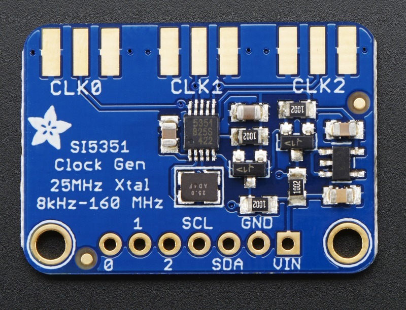
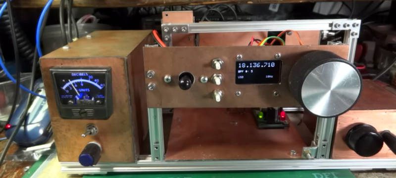
[Tom Hall], along with many hams around the world, have been hacking the Silicon Labs Si5351 to create VFOs (variable frequency oscillators) to control receivers and transmitters. You can see the results of his work in a video after the break.
 [Tom] used a Teensy 3.1 Arduino compatible board, to control the Si5351 mounted on an Adafruit breakout board. An LCD display shows the current frequency and provides a simple interface display for changing the output. A dial encoder allows for direct adjustment of the frequency. The ham frequency band and the frequency increment for each encoder step are controlled by a joystick. When you get into the 10 meter band you definitely want to be able to jump by kHz increments, at least, since the band ranges from 28 MHz to 29.7 MHz.
So what is the Si5351? The data sheet calls it an I2C-Programmable Any-Frequency CMOS Clock Generator + VCXO. Phew! Let’s break that down a bit. The chip can be controlled from a microprocessor over an I2C bus. The purpose of the chip is to generate clock outputs from 8 kHz to 160 MHz. Not quite any frequency but a pretty good range. The VCXO means voltage controlled crystal oscillator. The crystal is 25 MHz and provides a very stable frequency source for the chip. In addition, the Si5351 will generate three separate clock outputs.
[Tom] walks through the code for his VFO and provides it via GitHub. An interesting project with a lot of the details explained for someone who wants to do their own hacks. His work is based on work done by others that we’ve published before, which is what hacking is all about.


It is 25 MHz (mega Hz), not mHz (milli Hz).
Yep, how big an antenna would you need for a 28 millihertz signal, and more importantly, what would you transmit?
10714285.714285713 km ← that’s the approximate wavelength at 28mHz. I think I’d have trouble getting council approval to erect that.
Actually, come to think of it, I think I dispute the supposed 8kHz—160kHz range too. Seems out by a factor of 1000.
yeah if you look carefully at the breakout board it says 8kHz -160MHz
That would be for a full wave antenna. No-said he was trying to receive or transmit on the 8-160KHz range, but ELF antenna design is quite different and requires far less space.
“erect”. hehe
Easily solved by going for a quarter wave antenna
I showed my (veteran analog EE) dad the Si504, and he said it has way too much phase noise to be a serious ham VFO. I suspect the Si5351 has the same problem, but I don’t understand the specs well enough to know.
I’m not the J above. I think i’m going to change my nick to Jii, since there seem to be too many people using J as a nick. I’m the J, that has left comments especially in topics related to automation. So this is kind of an official announcement.
On another offtopic topic, i have nothing on topic to say, so i just wish the topic was “Teensy 3.1 Controlled UFO”.
Sorry about that, Jii. I should have looked around before I started using that nick.
I dont think phase noise is the problem with the si5351 it’s harmonic spurs that are the issue.
It is no worse than any other modern PLL based radio.
The phase noise of the PLL outputs can be higher than if only the internal dividers are used to divide down the 25MHz clock, but as Mark said, it is no worse than any modern PLL based radio. Harmonics are easily suppressed.
Phase noise isn’t an issue. http://soldersmoke.blogspot.ca/2015/08/si5351-phase-noise-tale-of-3-oscillators.html
It may not be an issue with traditional designs but when you are using them to drive a tayloe mixer (as is the case in many modern homebrew SDR designs) phase noise is indeed a very big deal.
sigh.
actually, no its not a big deal at all with a tayloe detector. works fine. Might be an issue if your aiming for a >20GHz transceiver, but it doesn’t seem to be a problem on my HF receiver.
Some other chips, like the AD9850, have worse phase noise, but still work fine.
Phase noise doesn’t multiply in PLL’s the way it does in analog frequency multipliers, so the phase noise is relatively constant across the frequency adjustment range. The mixer design makes no difference. The performance would be no different than any other modern PLL tuned receiver.
The phase noise makes no difference in this case because the LO is not being operated at the same frequency as the RF in. Phase noise on your IF makes little difference in this case, because it is in the audio frequency range and you aren’t trying to phase lock it to anything.
The hack rf one uses this chip… i wasnt aware it had phasing problems.
Maybe we should all use gold leaded teflon ac coupling caps and $20,000 hook up wire…..
This stuff isnt black magic, maybe people should read the data sheet and do research on the acuall chip in question before spreading rumors..
Phase noise is always a key consideration, especially above 15-20 MHz or so. The Si55351 is a pretty crummy part phase-noise wise compared with something like the Si570, which has plenty of open-source VFO software examples in the wild. But if all you want to do is build a cheap 40/80m receiver, you won’t notice the difference with the Si5351 (provided your receiver is designed properly of-course).
The “phase noise” complaint shows up frequently in regard to the Si504 and the Si5351 and I think a few others. The folks over at Solder Smoke seem to have put the complaint to bed last year (http://soldersmoke.blogspot.com/2015/08/fight-hiss-teria-give-si5351-chance-try.html). The article indicates measurements done showed phase noise at -130dBc/Hz at 10KHz, which is to say comparable, if not marginally better than some other common techniques used for oscillation.
IRL, it turns out that the phase noise just doesn’t add up to much. So, don’t let that bogeyman stop you from using and experimenting with these versatile chips!
It’s 160MHz not KHz in the article.
This is right people need to be more observant.
Thw hackrf one uses this chip and works well to 6ghz so i think that busts any rumors spread by people who cant read the data sheet….
If ossman followed your half baked un researched logic his sdr would have gold leaded teflon ac coupling caps and silver jumper wire..
Oooooh… an SDR for audiophiles!!! (cough, cough, hack, etc…)
Apologies for the frequency confusion. It’s fixed now.
That thing would also be handy for experimental overclocking of devices, replace the oscillator with a piggyback of this chip and see what can be achieved.
For those devices that they keep their technical data under a non-disclosure veil