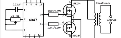
If you search the internet for 12 volt to mains AC inverter designs, the chances are you’ll encounter a simple circuit which has become rather ubiquitous. It features a 4047 CMOS astable multivibrator chip driving a pair of MOSFETs in a push-pull configuration which in turn drive a centre-tapped mains transformer in reverse. Not a new design, its variants and antecedents could be found even in those pre-Internet days when circuits came from books on the shelves of your local lending library.
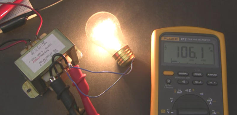
 [Afroman], no stranger to these pages, has published a video in which he investigates the 4047 inverter, and draws attention to some of its shortcomings. It is not the circuit’s lack of frequency stability with voltage that worries him, but the high-frequency ringing at the point of the square-wave switching when the device has an inadequate load. This can reach nearly 600 volts peak-to-peak with a 120 volt American transformer, or over a kilovolt if you live somewhere with 230 volt mains. The Internet’s suggested refinement, a capacitor on the output, only made the situation worse. As he remarks, it’s fine for powering a lightbulb, but you wouldn’t want it near your iPhone charger.
If this video achieves anything, it is a lesson to the uninitiated that while simple and popular designs can sometimes be absolute gems it must not be assumed that this is always the case.
We’ve featured surprisingly few mains inverters here at Hackaday. There is this Arduino powered one that uses a PWM drive, but that’s about it. [Afroman] however has provided us with plenty of entertainment. Here he is on the subject of boost converters, for example, or more recently building an FM bug.


408 Vpp is maximum I see in his video. That is 204 Vpeak or 144 Vrms. Not bad for such a design.
Correction: It is not 144 Vrms, since it is not a sine wave.
Yes that’s because I only ever ran the inverter while hooked up to the scope at about 7 volts input. If I ran it at the normal 12+ volts I ran the risk of damaging my scope or probes.
Makes me want to go and check my inverter to be sure it is not noisy or poor at regulating outputs. One built inside Saturn Relay minivan and one that plugs into 12v accessory outlet that claims to do 2A at 110v output
Afroman why did you take down your old pages :( I loved clicking through the Doom Monitor or Ahnuld pages during slow days :D
Thank you
What if addition to the cap on the AC output side, there were caps across the DC inputs to the transformer?
Might get some cancellation due to voltage overlap. Though the waves would be slightly less square
“Though the waves would be slightly less square” is sort of what I was thinking could / would happen.
Perhaps one or two caps across each DC leg to the center tap, and another (or two) across the DC legs themselves, maybe would slow the rise / fall times enough to be closer to sinusoidal and also limit some of the voltage overshoot when the system’s unloaded?
So which inverter circuit should the average tinker be building?
Does a decent one that doesn’t completely suck like this one become too complex for a DIY project?
something with a feedback loop…
Avoid circuits that comes with little or no documentation. i.e. no math, no actual documentation how the parts are chosen, no simulations, no scope pictures of the output under various loads. Fancy youtube video does not count.
You may skim over those because you can’t be bothered, but someone (i.e. the designer of the circuit) should be doing their homework.
I’m wondering the same.
Maybe with a proper RC filter both on the transformer input and output it would fare a bit better? As he said, the capacitor on the output puts it in the “this shit is almost acceptable” range.
Another sensible option would be ditching the 4047 and putting a microcontroller in there. I know it’s overkill but hey, you could implement some feedback and safety shutdown, have frequency stability, maybe crudely ramp down the voltage instead of suddenly switching off the transistor to reduce the ringing (although it’ll heat up significantly if you ramp it down too slowly)… You could even get a high-frequency transformer and PWM a sinusoidal signal through it instead of that horrible square wave.
Some old APC UPS use that sort of design. Maybe they use a transformer with well controlled leakage inductance to avoid generating spikes?
The problem is the fast rise time of the square wave. An ideal inverter would use a sine wave drive.
What about using a cap and a diode at the base of the transistors to smooth the rising of the square wave like here http://cms.edn.com/ContentEETimes/Images/01Steve%20T/LivAnaShootThru131/Shoot%203L.jpg
Not exactly like that, as that is to prevent shoot thru but in that configuration to only filter the rising of the signal.
you guys and gals do realize that the fast rise time is there so the mosfets don’t blow up?
You do realize that we’re talking about the high-side of the transformer, don’t you? All those harmonics and spikes get thrown directly into whatever’s connected to it..
The driver circuit actually has a slow rise/fall time – huge gate capacitance, high CMOS driver impedance and 100 ohms. Thankfully the operating frequency is low, so the slow switching do not contribute to much losses.
Completely wrong way of driving a MOSFET at anything in the kHZ or faster speeds.
I’m curious to know if a simple line filter (like the kind most of us have dozens of kicking around in a box somewhere) would clean most of the noise out of the HV side before powering whatever it is you’re trying to run..
The answer be a RC filter across the output. With the right component selection the R will absorb the ringing caused by transformer parasitic.
aka a RC snubber
Would some small caps between the MC and the MOSFETS not help smooth the wave edges. Possibly a larger set between the MOSFETS and coils too?
The FET drive circuit is fine, probably want some zener clamps on the FET drains (15V or 20V to the +12 Rail), also an RC snubber on the output and/or input of the transformer should take care of the ringing. The voltage sag is just because of the transformer impedance, not much you can do there without feedback.
Also going to want some sort of Y-cap or big-old resistor setup to keep from charging the output relative input voltage up to the transformer’s breakdown.
Make the transformer primary resonant at the line frequency (e.g., 50 or 60 Hz) so it acts as a band-pass filter. The result is a sinusoid. Whaddya tink?
The point of using high freaks is to reduce the size & cost of components. A 60 Hz transformer at 2 KVA and at resonance could weigh about 40 lbs and add significant cost.