A very good question came up on The EEVBlog forum that I thought deserved an in depth answer. The poster asked why would amplifier companies in the heyday of tube technology operate tubes in mass produced circuits well in excess of their published manufacturers recommended limits. The simple answer is: because the could get away with it. So the real question worth exploring is how did they get away with operating outside of their own published limitations? Let’s jump in and take a look at the collection of reasons.
Materials-Based Tube Performance
First a brief discussion of what the limiting factors are in tube performance. Heat and Gas are the two foes of tube design. Additionally both are dynamic in that heat will liberate residual gas from internal tube components and gas will interrupt proper operation and in the worst case scenario ionize and cause a gas short. In some tubes this can cause a runaway condition resulting in a complete failure. Remaining gas has everything to do with how the materials and parts used in the tubes construction were cleaned, processed, and how the evacuation was carried out, which in the case of most receiving tubes was marginal at best. It still is at most factories. Additionally if materials in the tube are not held to a tight tolerance (particularly in cathodes and grids), you can have leakage paths from metals evaporating from hot bodies and depositing on cooler ones. You don’t want this. Magnesium and Silicon which were common cathode reducing agents particularly in cheaper tubes is one of the largest culprits. It was used to speed the age in and stabilization of the cathode, therefore getting it out the factory door faster at the cost of possible tube leakage early in life. Cathode base alloys with these reducing agents were what were called “Active” cathodes. Other materials were used with greater safety margin later on but that is for another article.
The next consideration for heat is its removal. This has three facets. First radiating, or conducting heat from the anode to the container, in this case glass. Second is the carrying away of this heat from that surface via forced air or convection, radiation, or in some instances liquid or heat sink conduction. When many of these tubes were designed, blackened nickel anodes were the standard and the specifications were based on this. This type of material typically has about 70-80% equivalent of black body radiation and a relatively low heat conduction meaning you have concentrated hot spots in the anode radiating at counterpart hot spots in the glass, and glass being a poor conductor of heat you now have a situation of potential stress building up from heat differential in the bulb. Third you have heat removal in a more direct manner via the lead pins particularly in miniature tubes that are conducting heat directly to the glass/metal seal which is the weakest point in the tube, and then on to the socket contacts themselves.
In the 1960’s better multi layer materials became available that would allow greater anode heat conduction therefore spreading the heat around more evenly before radiation. These materials typically had copper plated onto them at some point adding to its better heat conduction distribution properties.
Aluminized layers taking advantage of special heat treatment made for more efficient heat radiation. This is the grey material used in anodes for the later half of the tube years. Many flavors of this kind of material were used with the highest performers belonging to Texas Instruments materials division and selling until the mid 90’s under the name AlNiFer. It was a multi layer steel, nickel, copper, and aluminum clad product made much the same way quarters are here in the US. Many tubes today use a anode of steel plated in nickel with an aluminum based coating forgoing the copper layer. These, along with other improvements in the areas of cleanliness and processing techniques led to greater tube performance as the years went on. As these technologies and processes were applied to the older tube designs their qualities were improved as well.
Conservative Ratings
Another major factor was the propensity of the tube companies to conservatively rate their tubes. Many engineers knew this and would use it to the advantage of their own designs. I have been told by former General Electric engineers that they looked at this as a selling advantage in so much as they would boast about the extended capabilities in their products and would in fact distribute engineering only data sheets and data sets telling the design engineers how to tweak their designs for maximum performance.
Now picture yourself as trying to have your product stand out in the market. As we all know in the audio business power sells and nothing is better than getting more power for the same price. Sure you could redesign your product with more robust transformers and larger output tubes, but that would cost money. Let’s not forget that specialty tubes such as the 7591, EL34, 6550, 5881, and 8417 were an order of magnitude more expensive than pedestrian 6BQ5, 6V6, and 6AQ5’s that were made by the train car load. You can take that 15 watt amp and have it crank out 20 watts by simply adding a few turns to the secondary of the power transformer costing practically nothing and when the tubes do fail those cheaper replacements will only be as far away as the nearest store. This was the game played.
Operating Outside the Curve
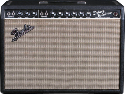
Those who I work with and talk to know I have never really bought into the myth and lore of the audiophile realm. I only base what I do on measurable fact. That is not to say there is no room for the subjective view point in my analysis but everything must be taken in context. There are what some would call “Sweet spots” in audio designs. I have found in certain designs these spots are often where certain parts and tubes are being used outside of their recommended ranges. Designs from Fender and Music Man come to mind. A Deluxe Reverb typically can place more than 400 plate volts on poor unsuspecting 6V6 tubes when the highest design maximum rating in any major datasheet (General Electric) is 350 volts. Empirical evidence shows us from the thousands of these units out there (many with their original tubes still working) that they could in fact handle this service. At a certain point we must conclude that the published maximum recommended specs are just that. Recommendations.
This Goes Beyond Tubes
In any product the surest way to become a failure, is to have failures. MTTF or “Mean Time To Failure is a mantra to the Q.C. engineer and it does not take a company long to realize it is much cheaper to fix problems before you build them rather than after the device is in the field. There is always a rainy day though. Bogey outlier parts must be accounted for and assumptions must be made in regard to how tolerant your product must be to external stimuli in field.
This is where we encounter the philosophy of what is sometimes called “head room” or “safety margin” in design. What is the best way to make sure a 1/4 watt resistor will always work and stay on spec? Ensure it can do the same at 1/2 watt. The idea is simple. Put a little more effort into the robustness of the design and save yourself a significant amount of early failures in the future. Engineers being the inquisitive sorts will often explore these extra safety margins and exploit them. This is usually dependent however on the market the device is being sold into.
You can literally bet your life a medical or airbag sensor device has been qualified and everything in it is within those recommended specs because when that lawsuit happens you can be assured any variance will be questioned again and again. Meanwhile those 1000 hour life electrolytic caps in that computer power supply stay on 24 hours a day 7 days a week as long as it is plugged in and seem to do just fine. It is all a matter of how much liability can be assumed in your particular application.


I sort of think that as engineering ability improves the specification of things does too. There is a railway tunnel near my home and in the 1970s a petrol train derailed in the tunnel and set on fire. It burned for the best part of a week and the ventilation pipes were like massive bunsen burners, truly a sight to behold. When they got to inspecting the tunnel several weeks later expecting that the line would never run again because they could never afford to rebuild the tunnel they discovered that the tunnel was 7 layers of brick thick and the heat had only penetrated 2 layers, structurally the tunnel was still absolutely usable. It was designed and built by Stephenson and had, what was probably normal for that age, a huge safety margin in the original design.
As time goes on that safety margin is reduced as it costs a huge amount to design for the exception though they do still have to do it in a lot of cases.
Nowadays electronic component safety overhead is as near to 0 as you could get.
A former employer explained the perceived robustness of older mechanical designs as the result of “which side of the cursor (on the slide rule) the engineer went with.”
Another one is old military designs. I have a number of WWII era Army generators we use around the farm, because they’re bulletproof and easy to work on. They used overbuilt components to start with, then derated by a significant margin. For example, the PE-95-A genset we’ve got is a 7.5 kW Onan unit, which the Army rated at 5 kW. You can reliably get 10 kW out of it with no stress to either the engine or the alternator.
I think the takeaway is probably that engineering wasn’t as precise in the olden days, often because of the tools and design/simulation techniques, so engineers and companies that wanted to stay in business made sure their calculation errors were on the overbuilt side, not underbuilt.
The other side of this is that the test protocols required to qualify these were pretty general (eg. “Run 1000 start-stop cycles with total 500 hour run time in all conditions, disassemble and check for component wear/failure”). If it broke or wore prematurely it was beefed up. Rinse and repeat.
Current tests are much more specific, so “design for the test” is more easily attained, and occasionally cheated (think VW Diesel here). This isn’t necessarily always a bad thing – the downside of overbuilt is weight, bulk, time-to-market and material cost.
That reminds me of the testing regime for the WWII-era Merlin aircraft engine (Spitfire, Lancaster, P-51 and others). Run it at full throttle until something breaks, re-engineer or strengthen that component, and do it again.
Older stuff WAS more robust not just because of cautious engineering but also because in many cases they were trying to establish a market for a new technology and reliability was going to be a huge factor in gaining public acceptance. Some old fridges made in the Fifties are still slugging away (albeit in the basement as the beer fridge) whereas modern units rarely last that long for example.
Just replaced a Haier fridge from 2009 with a Hotpoint from 1954. Haier had shredded nylon hinge bearings, a split magnetic seal, and it leaked water all over the place. The Hotpoint from 1954 just works and uses less electricity to boot!
Hotpoint is an ironic name for a fridge :-)
But did you really test energy consumption in comparison to the Haier unit when it was new or another new fridge?
One cannot fail to note that it is only the examples that SURVIVED to this day are the very ones you observe to be robust.
The shoddy stuff got thrown away years ago.
To some extent that is true, but then there are cases like the DC-9 examples of which are still in service at fifty years old. Yes they have had work done, but they were a very sound airframe right from the beginning, and like McDonnell Douglas’ other iconic aircraft, the DC-3 will be flying just about forever.
I had never heard of that tunnel fire, but it sounds like it was the biggest such fire in history.
https://en.wikipedia.org/wiki/Summit_Tunnel_fire
http://www.manchestereveningnews.co.uk/news/local-news/remembering-summit-tunnel-fire-30-8315156
http://www.firewestyorkshire.com/summittunneldec20th.htm
It seems that this is the original discussion, and an interesting one at that.
A link to the EEVblog post in question (first sentence of the article) would be nice.
Or a link to Adafruit.
Another factor is that with more modern and complex parts the spec is usually based on the assumption that you have all subsystems in operation and you need all outputs to meet spec. If your specific application doesn’t use subsystem Y and can tolerate out-of-spec waveform shape on output Z, is is possible that you can exceed the published spec on subsystem X if the limit for X was set so it wouldn’t push Y and Z out of spec.
For instance, you can over clock the GPIO subsystem of a PIC32MZ micro to 400% of its published maximum if you A) don’t need the JTAG function that shares some of those pins, and so long as you don’t expect clean square waves on any output pin that you push more transitions to than the maximum clock rate it is specified for. In my case I clocked it at 200MHz (spec said 50) so I could push a new value out every 5 system clock cycles to get my 40MHz pixel clock. So my over clock was to make the internal DMA state machine’s 5 system clock period harmonize rather than jitter against the clock rate of the GPIO peripheral.
400% is pretty crazy, and it may work sometimes. It probably won’t work over the full temperature and supply voltage range, and it probably won’t work for every device. If you only need 1 to work in a limited range of conditions, for hobby purposes, you could get away with that, but it would be a very bad idea to do this in a commercial design or something that really needs to work.
I recall Rigol used ADC way out of spec in their DS1052 scope (clocked at something like 4x the rated speed).
If you know where to look. you’ll find tubes in service right now, all over the world doing things solid state simply cannot yet do. One thing “tubes” are very good at is amplifying microwave and mm wave frequencies with extreme power output because they can operate in that range without melting down. The components are larger than the wavelengths they are dealing with and that makes it pretty trivial to get rid of the heat that’s produced. SS has to be smaller than the wavelength and getting heat out of parts that tiny is a nightmare. But yeah, a lot of tube specs derate the tubes right out of the box. One of the reasons is the nature of tubes being so variable in their construction and operation tube to tube off the assembly line. Sort of like silicon wafers in processors. Some will clock well beyond spec, others will choke a tiny bit past nameplate. Just the nature of the beast.
The size vs. wavelength has not much to do with heat rejection. There are also semiconductor components which are bigger than the wavelength in the material. A Gunn-diode even relies on run-time effects in the semiconductor.
But of course its a question of power density and waste heat vs. component size. And of course a simple iron “plate” can tolerate more temperature than a delicate semiconductor structure.
Vacuum tubes often had to ratings, the commercial rating, which assumed continuous usage and the ICAS (intermittent commercial and amateur service) which assumed that you would push them hard, but not all the time and that a higher failure rate was ok. The ICAS rating was the result of ham radio operators pushing the tubes well beyond the design ratings.
So THATS why Scotty could always get the Enterprise working when he said “Capt’n, she canna take any more!”
Those 1000 hour electrolytic capacitors on PC motherboards are a specific case. The lifetime of an electrolytic cap depends a lot on its working conditions. The most important factor is the ambient temperature. As a rule of thumb, the capacitor lifetime is halved every 10*C of temperature rise. This means that using 105*C rated capacitors instead of 85*C ones makes them last approximately 8 times longer in same environment. Like Dave would said, “Go figure!”.
Another thing is aging due to resistive losses on the capacitor’s ESR. If by design (like SMPS) the cap will live a harsh life, gulping amps worth of pulses, make sure it is rated to withstand that and more “and Bob’s your uncle.” ;)
The flip side of all of this is that you want lower cost, the thing that has to be compromised is lifespan. In general, more materials make for more robust components and this for longer lifespans, and the reverse is true. For example if you build an electric cooker out of thin steel sheet, and thin wired elements, it will work, but rust will kill it sooner, as will stress on the thinner wires in the elements. My parents have a cooker from 1928, that is still fully functional, the fireplaces in my house are cast iron and made around 1875. Both work. The chain store bought electric fan heater I recently threw away was less than five years old.
Modern designers are constantly being pressed for the next model and the next, so “cheap” and “fast” triumph over “good” in the classic management triangle. ( https://en.wikipedia.org/wiki/Project_management_triangle ) – when it comes to life support systems, as opposed to “disposables” like cookers, “good” becomes the dominant factor.
Pushing things beyond their design limits is much more risky with a flimsy lightweight “disposable” item than it is with one that is well engineered.
Studying failure modes to improve design rarely matters when you get in to the “stack ’em high, sell ’em cheap” dynamics of consumer capitalism, but if you are building for harsh environments, or safety critical systems, it should be central to your thinking.
A 0.01% failure rate in artificial heart valve is unacceptable, but a 1% failure rate in the latest must have shiny tech. that will hit the landfill within 2 years probably barely dent the profits.
That’s awesome that tubes had that much safety margin! I’d be careful about using the same logic in modern components – with the advent of better simulation tools, the consensus safety margin has gone towards zero. In the case of cheap no-name components, it’s almost certainly gone negative (in fact, I assume “negative margins” on the ratings of any cheap no-name Chinese components I design in, particularly SMPSes…)
It is surprising how hard you can push vacuum tubes. My power amplifier designs have pushed EL34’s fairly hard for class AB, but i’m sure others have squeezed even more power out of them. http://hackaday.com/2014/06/04/keep-those-filaments-lit-design-your-own-vacuum-tube-audio-equipment/