Mechanical drawings are an excellent way to convey design information, and while sophisticated 3D modeling is slowly taking over, with some companies accepting files over drawings, the mechanical drawing remains the written contract so to speak for complex parts with tolerances and non-modeled features.
But if you didn’t take a technical drawing class (typically Engineering Drawings 101), how do you learn? Well, if you have 15 minutes, this is an excellent video, which speaking from experience, covers the basics from the 101 course.
The lesson covers all the basics, from 2D projection, multi-view drawings, isometric projection, cross sectioning, linear dimensioning, basic tolerancing and alternate views.
Narrated and taught by [Chris Guichet], the reviews are in:
“Top notch video. Clear and informative, lots of good information here. (Source: 20+ year draftsman)”
– Roger Haley, YouTube
“Just skimmed through the three sections. I’m really impressed, you probably covered 50% of a GD&T course in 15 minutes.” – Yamugushi, Reddit
And speaking personally as a mechanical engineer, I’d have to agree.
[via r/engineering]


Solidworks does this from a model in literally seconds
If you know how to make a proper engineering drawing then yes, you can make a good drawing in solidworks in very little time indeed. But don’t even for a second think that if you don’t know the basics you’ll still get a good drawing from any CAD program!
Making clear unambiguous fully dimensioned drawings that give exactly the information needed is certainly a skill. It’s not that hard on basics parts, but once things go more complex it starts turning into a dark art.
A skill in short supply. I remember a time when companies had drawing offices filled with earnest young men in short-sleeved shirts with pocket protectors who produced and maintained technical drawing that were real tools. When CAD first came in it was those that had come up through that system that used it and nothing much changed, as they retired however, things started going downhill and quality suffered. I glad my working days are behind me.
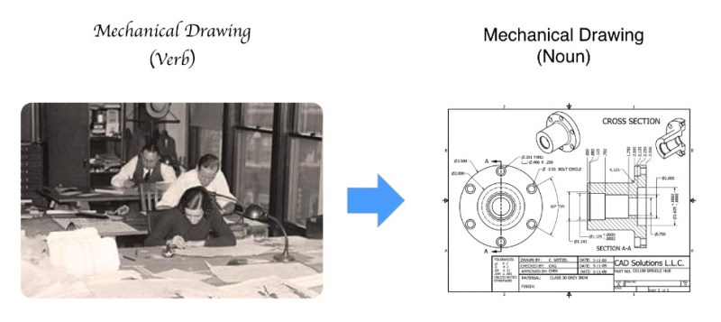
Not like in the above photo then ;-)
Not a short sleeve shirt in sight….
I think the above foto of mechanical drawing (noun) is of a design department. The actual drafting (Which would be the correct term) was usually done in the drafting department on those tilted tables with a drafting machine or T-square. Where they produced those beautiful meticulously drawn blueprints. Where you could identify the designer of a part by the handwriting of the legend or the style of dimensioning leaders. Looking at 120 year old 1:5 plan drawings of a steam locomotive is more like looking at a work of art than a technical document.
(BTW, I’m only 28, and have only ever worked with CAD programs. I really wish we had learned hand drafting before CAD. I actually put some effort into teaching myself how to do it right. Some of the crap my fellow student and even now some of my fellow engineers dare to call a parts drawing makes me cringe. Once I finish by new hobby room I plan on installing a drafting table, just for shitz, giggles ‘n relaxation)
In reply to [ThisGuy]
I took a Mechanical Drawing class my second year of High School.
I liked it, but I couldn’t get an “A” because of the smudges I left on the drawings…
I still have my eraser shield (somewhere).
I do remember my Dad hungry and focused with a Autocad ver 1.0 Xeroxed Manual and oddly bound A3. There were indeed draftsmen that couldn’t deal with staring at CGA and EGA CRT’s. And engineers who couldn’t deal with staring at CGA and EGA CRT’s.
Can’t blame them. Dad was suffering from migraines every day.
http://farm2.static.flickr.com/1233/1288243739_7aa2c15928.jpg
It’s also important to know WHO you’re making the drawing for. I’ve run into this on several occasions working with different machine shops, since each of them has different CNC machines with different capabilities and how they’re programmed (for example, dimensioning the centers of filleted corners versus dimensioning the tangent lines to those fillets).
Usually, if you help the shop out, they’ll make your part faster. ;)
He might be talking about the ‘auto dimension’ feature, which picks up dimensions directly from the model. Usually just creates an unreadable mess.
+1
Autodimension is only good if you want to be sure the machinists will hate you and the parts will be unusable :)
As an engineer I can guarantee you that making a good drawing often takes more time than making the 3D model itself. There are parts that take a full day to make a 2D drawing of, even though drawing it in 3D only took a few hours. A tool like Solidworks makes it a lot easier, but that does not mean that it is simple.
After weeks of training and thousands of dollars in purchase and support.
How much do pencils cost and how many people know how to use them?
Solidworks users can screw this up in literally seconds.
Yeah if you HAVE Solidworks.
Good intro, I always add shaded isometric views to my drawings (sometimes even images of the part if it has been made before). Even if the wire frame views are unambiguous and fully dimensioned it never hurts to just show someone a picture their brain can immediately understand.
Good to know I’m not the only one.
On occasion, I’ll also put in an exploded assembly if the part is complex, so that the machinist can see how it all fits together. Sometimes, I don’t always have the best design, and the machinist can suggest design modifications that make the part better as well as easier to make.
Yes! Rule #1 of getting a design manufactured, ask the manufacturer to suggest changes. Like if I forget to add an inside corner fillet, please don’t EDM the part because you think it’s impossible to make any other way, just call me and ask for a fillet. In fact, I should add a permanent footer on my drawing template “Do not hesitate to suggest changes that can simplify manufacturing”
I once watched a Patent Lawyer while he was working on one of our inventions…
He was a full degreed Mechanical Engineer as well as a Lawyer.
His isometric drawings were beautiful…
It’s a general requirement that Patent lawyers have a technical degree, if not doctorate before they can specialize in patent law.
Ya that would have actually totally solved it. Good suggestion. (videomaker here)
One missed opportunity for explanation that is one of those very annoying gotchas for those of us who work with international drawings is the difference between first angle and third angle drawings/views. The way projections are placed can have a big influence in how the reader interprets the drawing. And the difference between first and third angle basically means parts seem mirrored from on to the other. Even though they are the same part.
When working with a CAD program and you have the space on the page, include an isometric view of the part, this will often help alleviate any misinterpretation (And would probably have prevented that “turned down instead of flats” problem mentioned in the video)
As an engineer I’d advice anyone who is starting out with a CAD program who has no experience in mechanical drafting to first take an afternoon to sit down with a piece of paper, a pencil, a ruler and a few simple object and just practice making drawings by hand. It’ll give you a much better feel for how a drawing is built up. The next day, look at your drawing again and imagine you are now in the machine shop and have to make something to that shape. Are all the lines there? Is the dimensioning clear and unambiguous? Are the tolerances correct? Can you actually make that? Maybe ask someone else to look at the drafts you made and see if they can understand it. What is clear to me as the designer could be clear as mud to someone else.
Good advice. This is really relevant to giving any kind of instructions for assembly, for a user’s guide, or other documentation that someone else will have to use to perform a task. You have to imagine someone actually following the instructions. So many people screw this up, leaving out critical information – maddening.
Videomaker here. Good point, I was thinking of mentioning first and third angle conventions in the video, but my goal was to get people drawing as soon as possible, and didn’t want to slow down the flow to talk about conventions. 15 minutes is already a lot of time to ask for someone to pay attention to something.
Thanks for the reply. I can see the problem. Explaining first and third angle is probably going to take another 15 minutes :) . When you really start looking at doing this “to convention” there’s a LOT of things to explain. (leader lengths, gap widths, centerline gap/stripe/dot ratios, annotation placement, BOMs, page legends, line weights, to name but a few). Might be a bit much for a primer video
Mechanical Drawing
(Misunderstanding)
http://www.popsci.com/sites/popsci.com/files/import/2013/images/2012/02/sketchbot.jpg
Kuul! is that a Kuka?
Skip to 3:45…
“…We want to see the length of the shaft and the thickness of the head…”
heh… heh…
Ahh I didn’t catch that o_O
https://www.amazon.ca/Guide-Standards-Conventions-Graphic-Representation/dp/2553016700/ref=sr_1_2?ie=UTF8&qid=1459375770&sr=8-2&keywords=andre+cincou
A nice and costless helpful guide to have. Clear, easy, well documented.. Using it for the last 2 years… Enjoy !!
If you wish to pick up old-school mechanical drafting skills there are some wonderful free books here, https://archive.org/search.php?query=subject%3A%22Mechanical+drawing%22
Such as:
https://archive.org/details/mechanicaldrafti00milliala
https://archive.org/details/elementsofmechan00titsrich
The isometric views in engineering drawings look beautiful
I’m grateful that I was taught draughting concurrently with CAD
I learned the basic of technical drawing in the 7th Grade. We where tortured with this first on Paper then with a very easy CAD program.
Maybe a Germany thing.
Long before I had such fancy things as 3D modeling software, I used to do freehand isometric and 3 or more view drawings with nothing other than a steel ruler and a pencil, for fun.
Mark a baseline, measure out some alignment tickmarks, set the ruler angled just so then lightly draw a cube etc of the maximum dimensions of the item. Then start marking out to ‘cut away’ all the parts of the object not part of the final piece.
I took a drafting course in the 90’s and since I finally had a t-square and triangles I checked some of my old stuff, much of the drawings I’d gotten the 30 degree angles pretty near perfect.
I used to draw and sketch quite a lot, many cars and aircraft and spacehips… still have a box with a bunch of that stuff somewhere.
Fantastic video! Some happy memories of college drafting classes there!
Harold, BSME, PhD (Materials Science), says, I remember this fondly. This is what I was taught in Mechanical Drawing at CCNY in 1961
I’m in 3rd year Mech currently, and I am very glad for two things:
1) I worked construction for a few years, interpreting drawings and dealing with the tradesmen who have done the same for years.
2) I was forced to take a drafting course in 1st year, 2 months of pencil on paper, 2 months of 2D CAD.
Both have been invaluable. Many of my classmates have a heck of a time properly dimensioning components, and don’t even think of asking a machinist for input. The Solidworks model might take a couple hours to finish, and then I dimension it manually as if I were going to make the part (sometimes I end up doing that). Then I go talk to a machinist about the drawing. He tells me what he likes, what he would change, and what he dislikes. Why on earth would I NOT want to hear what the guy with 20+ years experience thinks is best?!
I would love to improve my manual drafting skills though. Basic napkin sketches and more detailed drawings… it’s useful to be able to sketch a concept in 30 seconds on a piece of paper to properly explain something, and my perspectives still aren’t that great.
Man, so much to learn so little time!