From the very first RepRaps to the newest and latest printers off the Makerbot assembly line, nearly every consumer 3D printer has one significant shortcoming: it cannot recover from missed steps, slipped belts, or overheating stepper drivers. Although these are fairly rare problems, it does happen and is purely a product of the closed open-loop control system used in 3D printer firmware.
[Chris Barr] has come up with a rather clever solution to this problem. He’s designed a system that will detect and correct problems with the mechanics of 3D printers. It’s technically not a closed-loop control system, but it does allow him to get the absolute position of a nozzle on the build plate, detects error states, and can automatically calculate the number of motor steps per millimeter. It’s also much simpler than other closed loop control systems we’ve seen in the past, requiring only a few bits and bobs attached to the axes and to the printer controller board.
[Chris]’ system uses a magnetic encoding strip, a single chip, and a little bit of support circuitry. It’s actually not that much different from the moving axis on a desktop inkjet printer. It’s not closed loop, though; the firmware hack is only a ‘basic error correction’ that moves the nozzle back to where it should be. Although this is somewhat of a kludge, it is much simpler than refactoring the entire printer firmware.
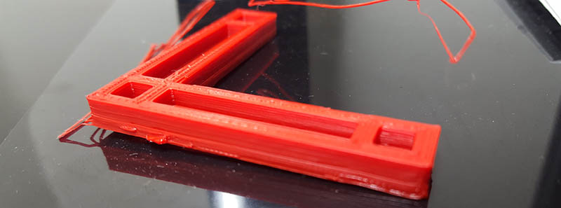
In the video below, [Chris] demonstrates his solution for error correcting the printer by jerking his axis around during a print. The nozzle miraculously returns to where it should be, producing a usable part.


“it does happen and is purely a product of the closed-loop control system used in 3D printer firmware.”
should read open-loop?
The same reaction I had. But rereading, maybe the statement is about the control code in the firmware being “closed loop” and not “open” to feedback.
That’s not how that works.
If you have optical switches, one can also just home the XY axis on an open-loop system for each thin Z-layer.
Most errors on modern printers are caused by Micro-stepping with cheap motors, dubious stepper drivers, and the wrong power supply. While it makes the motors quieter/smoother, most default driver configurations cause lost 1/16 step position data as the torque drops below 10% of the motors normal rating. Therefore, if you ran a lower resolution half-step mode one could get around 70% of the stepper motors torque rating, and would be less likely to lose micro-position steps at low speeds. It is an issue that the Marlin firmware quietly attempted to handle by multi-incrementing the motors per cycle at higher speeds, but it really depends on the printer hardware.
In general, this issue means that most FDM RepRap variants will have surface defects even if the mechanical jog is reduced below the driver positioning errors, and this project will still unlikely be unable to correct position to match theoretical limits.
I think it is great that people are working on the problem though, and as always we will assist when we can.
karma +1
=)
I don’t know if you have a 3D printer, but I do.
Failed prints happen when the plastic curls up during printing so that it ends up higher than expected. Then during the next layer the print head will bump into the plastic. Either that bumps the part off the printing bed, or the stepper skips a few steps. There is are a few things you can do about the part being bumped off the bed. Mostly make it stick better. But this solves the other problem: Missed steps due to the print head being stuck against the object at some point in the print.
Now it could very well be that YOUR prints fail on YOUR printer due to entirely different reasons, but I have certainly seen the failure-mode that this solution solves.
Of course, as you can see in the video, the part won’t be perfect. But in many cases you don’t need perfect, you just need “working”. Then the difference between “failed, need to start over” and “doesn’t loop pretty but it works” becomes important.
No need to yell kid,
Object deformation is usually more pronounced with exposed ABS, incorrect temperature cycling, and bad slicer settings.
Note, I use ABS because most other plastics available locally seemed to make fragile parts.
1. We use a heated build chamber to build with 3 layer wall thickness (3*0.4mm), 45′ cross hatch fast infill, and 0.25mm layer heights (a bit of custom gcode gets inserted in for the auto zeroing)
2. Having a heated bed is usually not enough: Mine likes to run hot at around 105’C with the RAMPS, but it will indeed vary with the filament source/age/water-content/sensor-readings. Some use hairspray/tape/Kapton/wishful-thinking, but we put a thin layer of cyanoacrylate on the glass bed (ours has a sealed build chamber). Note, you will need to drop the temperature back below 30’C to remove the parts or the glass will break before the part comes off. When bed cools, I simply clean off the surfaces with a razor.
3. I use a 100W work-light-bulb around 20cm under my spool hanger on the outside of the build chamber. This preheats the filament, and seems to reduce steam blow-outs from old filament.
4. If you are just beginning to learn about FDM, than simply ask for anecdotal feedback from those that probably already tried what you are doing wrong. There are many counter-intuitive solutions to common problems that often contradict what many websites document as best practice. A few friends and myself spent several hours reading about other peoples work http://richrap.blogspot.ca/ , and it still took about 3 weekends to start getting reliable 3D prints out of the Prusa due to several bad firmware versions floating around.
It was worth it though, as after awhile you’ll develop a sense for tweaking the FDM process.
Sometimes people just get some bad filament full of crud that will clog the extruder, and you’ll spend most of your time pulling apart the feeder to fix the issues.
You are welcome =P
“it does happen and is purely a product of the closed-loop control system” should read “open-loop control system”.
Standard Marlin firmware is open loop. It is capable of using encoders but that isn’t usually implemented. Even encoders on the stepper shaft don’t detect belt slips. Most common solution is to overdrive the steppers to prevent slipping.
I like this solution but adding more load to an already overloaded processor will cause other issues like stepper chatter that are caused by running a real time application without using a real time operating system.
Indeed. Time to drop Arduino for a 32 bit solution ;)
FWIW, Arduino supports 32 bit chips too. Duet and the upcoming 32 bit RAMBo, and maybe a few others use Marlin through the Arduino system.
You’re correct, a lot of my earlier attempts on the firmware side slowed the printer down to the point of being unusable. The solution employed in the video isn’t the prettiest, but it does have fairly low overheads from what I’ve seen so far.
With a faster microcontroller, I’d be interested to try something closer to a proper PID controller (or similar). The neat thing about this project is that it’s really two parts – the encoder module and the Marlin firmware modifications. The encoder module is more than capable of being used in a PID control system, the only thing keeping this system as it is is the printer firmware – which is always open to change.
” It’s not closed loop, though; the firmware hack is only a ‘basic error correction’ that moves the nozzle back to where it should be. ”
Just because it’s not PID or some other continuous system doesn’t mean it isn’t closed loop. It’s taking a measurement from the actuator and using that to change the position of the actuator – that’s a closed loop.
That said, what happens when the decoder misses a step?
Closed loop requires that you make an input and then measure the error on the output. Stepper motors are open loop systems. You have no way of measuring error and no way of checking if they responded correctly to your input (try driving one too fast for example).
“Stepper motors are open loop systems. You have no way of measuring error”
Unless you put a magnetic encoder on it. Which is what [Chris] did!
If I’m reading the firmware correctly, though, it actually doesn’t look like it’s closed-loop at the controller level. It looks like it has the [I]capability[/I] to be closed loop, but it’s implemented as discrete commands to measure/correct errors. So at the actual ‘machine’ level, it could be functionally closed loop, but the actual controller movement is open loop.
I’m not sure I see any advantage to that, though. I don’t know why you wouldn’t just have it continually correct movement.
Any control loop that takes discrete measurements as feedback is running “open” between the measurements.
Take for example, if you’re using an optical mouse sensor to control a X-Y table, you have to poll the sensor. You don’t know that the table has moved until the data comes back with something greater than zero, and you don’t know how fast you’ve moved until you poll it a second time.
The problem here is that if you’re trying to move the table very slowly, and you’re polling the sensor say 200 times a second, you won’t know how fast you’re going until 10 milliseconds later, and that’s a long time. Your motor might be running up way too fast and overshoot the target speed. Then you have to brake hard and that causes oscillation. Suddenly it becomes rather difficult to stay on track and the whole system becomes unstable, especially if your mechanism tends to stick and requires a little nudge to get it moving.
Continuously feedback isn’t necessarily better. You can be better off doing things blind and then seeing how much you got wrong, and then adjusting. That way your control loop doesn’t go apeshit on trying to correct the smallest errors it can detect.
you would only need to check for error between layers. the layers themselves would print in open loop mode. you might slip a step every now and again, but errors are going to be small enough and infrequent enough that you just need infrequent corrections. with how well the open loop positioning works, it would be overkill to run the thing in constant closed loop operation. a swipe over the offending edge with a deflashing tool would me more than sufficient to clean up the finished print.
Wouldn’t that depend on how complex the layers are? If you’ve got a mile to go, going an inch wrong at the beginning can cost you a yard by the end.
Thanks, I think I agree with what you’ve said here. At a hardware level, I believe this system is capable of closed loop control (processor speed notwithstanding).
I decided to go with a very basic approach to control, both in order to get something simple up and running quickly and to avoid adding any unnecessary overhead to the Marlin codebase. In practice, this feels quite responsive – the error is measured several times per second, and any motion that needs to be made to correct for the error is continuously applied by an interrupt interacting with the low-level stepper driving.
There’s a lot of room for improvement, and I’d like to explore that further. I am keen on maintaining full compatibility with the master branch of Marlin though, which means I have to tread carefully as I’m still trying to get my head around how everything works. Other firmware / faster control boards may be more conducive to exploring proper closed-loop control, but I don’t want to alienate the large number of people using Marlin and 8-bit control boards.
Good point – I think Brian wrote it that way because I mentioned somewhere the system “wasn’t proper closed-loop control” or something to that effect. I meant to say it’s not a PID controller, or any sort of full-fledged continuous system. I’m eager to explore better control arrangements, but my tests so far indicate I’ll need to shift to a faster control board (and thus different firmware) to do so. My early attempts at other control systems pretty quickly brought my printer to a near-halt.
As for missing steps, good question. I don’t have any error-correction on my error-correction, so the system wouldn’t detect that the encoder has missed a step. That being said, in my testing with the encoder module it doesn’t seem to miss any steps until I drive the axis above ~ 350mm/s, and I think most printers would travel at speeds below this when in use.
My test method was crude – I had an axis equipped with the encoder moving back and forth for two hours at a range of speeds. At the end, I then compared the position reported by the encoder to a value I measured with digital calipers and to the position the printer firmware thought it was at. Below 300mm/s all three would agree, 300-350mm/s I would occasionally see the printer miss a few steps (varied with acceleration I tested with), and above ~ 350mm/s I would see the encoder lose steps.
Losing steps is a misnomer, as the limiting factor is actually the onboard AVR that tracks the encoder to within one magnetic pole-pair (2mm in this setup). Failure occurs when the AVR doesn’t read the encoder fast enough, and we see aliasing so that the AVR interprets the direction of motion incorrectly. This means the smallest error that occurs is roughly 2mm, which was easy to detect.
Is 2mm precision actually enough to catch subtle errors and missed steps in the print?
Or is it just the coarse resolution of the strip, and the sensor is capable of finer resolution?
Thanks for the question!
2mm is the length of one pole-pair on the magnetic strip (each pole is 1mm). The encoder IC reads 4096 steps across a pole pair, or ~ 488nm / tick. I found that there’s a bit of noise with my current setup (I think due to bad placement on one of my bypass caps, hopefully corrected going forward) and in practice I’m seeing a useable accuracy of ~ 10um +/- 5um.
My current error correction only kicks in if it sees an error > 100um, in order to avoid transmitting this noise over to the axis. Filtering reduces the noise considerably, but as the axis is usually in motion the filtering causes the actual value to lag and throws things off. I’m sure there are solutions to this (sliding-window etc) but I haven’t explored them yet.
I’m unsure if there’s any perceivable benefit of significantly improving the accuracy / noise. The XY axes on my printer travel 12.5um / microstep, so provided I can get the value + noise below that I’ll be happy.
Cool. Bear in mind that the fine resolution is not reliable/linear between the poles because the poles may not be uniform, and the distance of the belt to the encoder, or external magnetic fields etc. will all thrown the reading off. For example, just the strip’s thermal expansion will throw your 0.5 µm theoretical precision right out of the water anyways. Suppose your have a .1% expansion – over 300 mm that would be a 300 micron error. 10 µm real precision would be excellent out of a setup like that.
“moves the nozzle back to where it should be”
Unless it’s a closed loop system, it’s not possible to do it reliably.
And even for a closed loop system you can’t correct everything, if you are missing some steps in one direction, you need to stop the nozzle right away, meaning latency should be low.
Same thing with a CNC, you need to catch the error very fast to avoid broken cutter.
I think his prototype has proven that it works well enough for 2d parts.
Bad choice of words perhaps – it is closed loop, as the position of the carriage is known at all times and this position is used to inform the printer firmware of where to move the carriage. It’s not a very good closed loop system though, as I’ve not implemented any proper sort of control system beyond a basic if error > threshold, axis += sign(error).
For subtractive CNC machines I think you’re definitely right. There, any mistake can damage the machine or create a faulty part.
In practice, I haven’t found this approach to cause any problems. In an additive process like this, provided enough of the layer is correctly deposited for the following layer to build on top of it, the worst side-effect will be artefacts on the surface of the print where the nozzle crossed the perimeter, and extraneous plastic strands outside the part (as seen in the video). Sure, if you’re manufacturing something that requires complete accuracy for the entirety of the part, this would not be ideal. If you’re printing something where you don’t mind cleaning up the external artefacts, then it could be useful. There’s no risk of damage to the machine here, unlike with a subtractive CNC machine.
This could be very helpful for reducing motor current. I have tried to reduce my Printrbot Simple Metal’s motor currents to get it to print more quietly, but eventually after a few hours or so you get a missed step here and there. So the solution / workaround has been to just keep the current and therefore noise and power consumption unnecessarily high. If my printer could recover quickly I’d be more than happy to move with whatever minor defect it caused if I could print while I do other things without the noise driving me (and those around me) nuts.
Thanks, this is exactly the sort of use case I’m trying to target. I know the current implementation won’t correct for errors that occur continuously / frequently, but for problems that might only crop up once or twice in a long print this means that they don’t spoil the whole print anymore.
We all run our stepper motors and drivers high enough to try and account for these infrequent problems, and as you’ve said that often means we’re running things at much higher power than we need to for 99% of the print.
Open-loop, like they said.
(quite) simple and efficient, nice work
i wonder why you go slowly back to the track?
Thanks!
Good question on the slow movement. To be honest, this was my first test with this setup, and I originally didn’t plan to share the video at all. I believe the system is capable of moving significantly faster, but I started off with a very low speed I hoped wouldn’t cause any problems.
I think that 3 of those ultra-cheap ebay calipers with digital display and serial output will make enough presision to close the loop. If they are too slow the can at least detect errors.
They too tend to miss steps.
The way the calipers work is by having a somewhat coarse quadrature pattern etched on a strip of PCB that goes along the track, and the slide counts how many stripes it has crossed, and tries to determine the exact position by sensing the phase angle of the pattern capacitively via how much the pattern overlaps the sensor.
The coarse measurement is more or less “absolute” within reason, but the fine measurement will drift around.
Open loop, Brian.
Stepper systems are ‘open loop’.. :)
Gah, heh, I see others also pointed this out.. Lol..
This really isn’t the way things *should* be done. If you look at any real CNC machinery used in factories or seen at industrial robots, they almost never use steppers. It’s all DC motors with encoders of some kind, be they magnetic, optical, conductive strip, restive, or involve rotating magnetic fields. The best way to do it from a control systems standpoint is to employ a DC motor, and encoder, and a PID controller. Instead the only place PID has been put use is in temperature regulation, which is ironic considering it’s rate of progression is low enough and it’s effect insensitive enough (with enough mass) that a simple on/off switch triggered by a window caparison would be enough.
And it’s not REALLY that hard, just unproven territory. It’s really easy/lazy to use a stepper, as you just tell the driver to move so many steps, and assume it’s done it. (this is part of why adding encoders to a stepper is fairly absurd) But, it’s not really that much more work to install a geared motor and an encoder to each axis, and drop in the Arduino PID library used for temperature to bring the motors into line. You’ll have to do some basic math to make it work, and some understanding of how a PID works is helpful (I can give a brief rundown of what I know for those who are interested), but in the end it means the printer tracks where it’s supposed to be in real time. You can even monitor it’s performance pretty easily if you tap into the current error value or output of each of the P-I-D terms.
Once people start to play with this, and put together a rudimentary package that can be mechanically substituted for a stepper (similar to a how-to on hot end construction), the barrier to entry would be drastically reduced.
Thanks for your comment!
I think you’re right overall – I’d be very interested in moving towards DC motors and proper control systems, and I think the community would benefit from such a shift in the long run.
My goal with this project was to come up with a simple way that existing printers and firmware can be retrofitted with a system that achieves some of the benefits of a proper closed-loop control system. The encoder module itself could be used to achieve closed-loop control of a DC motor, as it is also capable of operating as a rotary encoder. That said, there are probably better options out there for doing this – but this could be an easy way for people to experiment with a system that could ‘evolve’ from basic error correction with steppers to proper closed-loop control with DC motors.
I consider this system a stepping stone – it’s not where I think 3D printers should end up, but I think it’s in the right direction (particularly if it sparks interest in closed-loop control systems). Your mention of a stepper-compatible closed-loop motor package is interesting, and something I’d be interested in trying out. I have seen a few people try this before (search the RepRap forums for “closed loop” etc.), but I’ve not seen any of those systems make it into wide use. I assume this is due to cost, but I’m not sure.
The temperature cycling you describe used to be done, it’s called bang-bang in Marlin-speak and while it does work, you get more consistent results with PID on the heater. With a little tuning, the temperature swings are tenth of a degree or so instead of several degrees. I’ve tried bang-bang on a couple different heat beds too, same thing, I got better results turing on PID, the parts look better.
Servos on small machines like this don’t have the same payoff as they do on larger machines. It adds a lot of cost and complexity. I’m well aware that inkjet printers have servos but you’re talking about economies of scale that 3D printers just haven’t achieved yet. Consumer and hobby 3D printers are about in the 9 pin dot matrix era, relatively speaking.
Bang-bang is actually the correct term in control-engineering, so not just a fun word for marlin programmers :)
Wow, beyond honoured to be on Hackaday – sure made my morning when I woke up and saw this! Thanks Brian for the write-up!
I’ll read through and respond to any comments / questions I can. Thanks everyone who’s taken the time to share an opinion on this!
This is just a workaround. You have to find the reason of failed prints and fix it …
How about using the encoder strips and sensors used in HP and some other inkjet printers?
tyhis seams like a cool idea but i think it might be better to integrate it into the firmware. maybe keep much of the same setup but instead of using a second motor to return it instead tell the printer to pause and auto home the affected axis. I think this could done easily by hijacking the data pins for the on board controls most printers have and having a arduino pretend to be said on board controls