EPROM Timer

[glitch] had a cheap EPROM eraser with very few features. Actually, that might be giving it too much credit: it’s barely more than a UV light that turns on when it’s plugged in and turns off when it’s plugged out unplugged. Of course it would be nice to implement some safety features, so he decided he’d hook it up to a software-controlled power outlet.

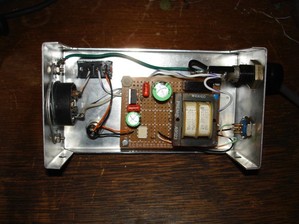
Of course, controlling a relay that’s wired to mains is old hat around here, and in fact, we’ve covered [glitch]’s optoisolated mains switch already. He’s gone a little beyond the normal mains relay project with this one, though. Rather than use a microcontroller to run the relay, [glitch] wrote a simple Ruby script on his computer to turn the EPROM eraser on for the precise amount of time that is required to erase the memory.The Ruby script drives the relay control directly over a USB to serial adapter’s RTS handshake pin.

[glitch]’s hack reminds us that if you just need a quick couple bits of slow output, a USB-serial converter might be just the ticket. You could imagine driving everything from standard lamps to your 3D printer’s bed heater (provided you use similar hardware), but it’s especially helpful for [glitch] who claims to forget to turn off the eraser when it’s done its job, which leaves a potentially dangerous UV source just lying about. It’s always a good idea to add safety features to a dangerous piece of equipment!

Put Words In Your Dog’s Mouth With A Talking Dog Collar

It’s just a little past Halloween, but Adafruit’s talking dog collar, modeled after the movie Up, is still a nice fusion between crafting and hacking.

One reason that Adafruit is so popular is that every time they sell us something, they give us some of the worlds best tutorials and libraries for free. For this project they’re using their Bluetooth LE board and their Audio FX board with a few more mundane vitamins to construct the collar. We’re sure the enterprising hacker could find alternatives if they so choose.

The collar is made of leather and 3D printed props. They went with alkaline batteries rather than lithium, to keep their doggy companion a little safer. All the electronics are hidden under the various props and the wiring is routed behind the belt. To control the app, the different sound bytes are mapped to buttons on their Bluetooth-to-serial phone app.

It’s a good starter tutorial, and the concept applied differently would definitely be good for at least one good prank on a coworker or friend.


Red Bricks: Alphabet To Turn Off Revolv’s Lights

Revolv, the bright red smart home hub famous for its abundance of radio modules, has finally been declared dead by its founders. After a series of acquisitions, Google’s parent company Alphabet has gained control over Revolv’s cloud service – and they are shutting it down.

Customers who bought into Revolv’s vision of a truly connected and automated smart home hub featuring 7 different physical radio modules to connect all their devices will soon become owners of significantly less useful, red bricks due to the complete shutdown of the service on May 15, 2016.
Continue reading “Red Bricks: Alphabet To Turn Off Revolv’s Lights”

A Look Into The Future Of Slicing

I’ve had a few conversations over the years with people about the future of 3D printing. One of the topics that arises frequently is the slicer, the software that turns a 3D model into paths for a 3D printer. I thought it would be a good idea to visualize what slicing, and by extension 3D printing, could be. I’ve always been a proponent of just building something, but sometimes it’s very easy to keep polishing the solution we have now rather than looking for and imagining the solutions that could be. Many of the things I’ll mention have been worked on or solved in one context or another, but not blended into a cohesive package.

I believe that fused deposition modelling (FDM), which is the cheapest and most common technology, can produce parts superior to other production techniques if treated properly. It should be possible to produce parts that handle forces in unique ways such  that machining, molding, sintering, and other commonly implemented methods will have a hard time competing with in many applications.

Re-envisioning the slicer is no small task, so I’m going to tackle it in three articles. Part One, here, will cover the improvements yet to be had with the 2D and layer height model of slicing. It is the first and most accessible avenue for improvement in slicing technologies. It will require new software to be written but does not dramatically affect the current construction of 3D printers today. It should translate to every printer currently operating without even a firmware change.

Part Two will involve making mechanical changes to the printer: multiple materials, temperatures, and nozzle sizes at least. The slicer will need to work with the printer’s new capabilities to take full advantage of them.

Finally, in Part Three, we’ll consider adding more axes. A five axis 3D printer with advanced software, differing nozzle geometries, and multi material capabilities will be able to produce parts of significantly reduced weight while incorporating internal features exceeding our current composites in many ways. Five axis paths begin to allow for weaving techniques and advanced “grain” in the layers put down by the 3D printer.

Continue reading “A Look Into The Future Of Slicing”

Hackaday World Create Day: April 23rd

It’s time to get out and have some fun with other Hackaday people in your area and we have the perfect opportunity. Be part of Hackaday World Create Day on Saturday, April 23rd. This is all about meeting others for an afternoon of creativity.  You might even find your engineering dream team! As part of World Create Day you’ll and brainstorm an amazing creation and connect with the people in your area that round out your own skills (electrical, mechanical, design, etc.).

This is the first ever worldwide event Hackaday has organized, and it’s made possible by all of the people who volunteered to organize a Hackaday Meetup in their area. We have heard from more than 100 of you so far and [Liz Krane] has done an amazing job following up with each organizer to get everything set up. You can still sign up to host (or co-host) and use the map to join a meetup already organized in your area.

We’re just getting started but the first added are in Ottawa Canada, Lagos Nigeria, Lynchburg, Virginia, and Puducherrry, India. We have more on the way in Malaysia, Greece, South Africa, India, Cyprus, New Zealand, France, Mexico, China, and many locations in the USA.

We’re sending out World Create Day sticker packs — created by [Joe Kim] and [Michael Guilfoil] — as fast as we can set up the Meetup pages. We will be on the lookout for Hackaday Meetups and World Create Day projects to feature right here on the Hackaday front page. Carve out 4/23 from your calendar and get excited, you don’t want to miss this!

Reverse-Engineering DebugWire

Has this ever happened to you? You start out on a reverse-engineering project, start digging in, and then get stumped. Then you go looking on the Internet for help, and stumble across someone who’s already done exactly what you’re trying to do?

[Geekabit] wrote us with a version of this tale of woe. In his case, the protocol to be reversed was Atmel’s debugWire protocol for debugging on low-pin-count parts. There are a number of websites claiming it’s “secret” or whatever, but it actually looks like it’s just poorly documented. Anyway, [RikusW] seems to have captured all of the signals way back in 2011. Good job!

The best part of [geekabit]’s story is that he had created the Wikipedia page on debugWire himself to inspire collaboration on reverse-engineering the protocol, and someone linked in [RiskusW]’s work. When [geekabit] picked up the problem again a bit later, he did a bit of web research and found it solved — on the page that he started.

Maybe it’s not a tale of woe after all, but a tale of unintentional collaboration. Anyway, it serves as a reminder that if you’re interested in the destination more than the voyage of discovery, it never hurts to do your research beforehand. And now we all know about the low-level details of the debugWire protocol. Anyone written up a driver yet?

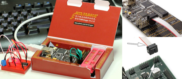
Thanks [geekabit] for the tip and the story! Image from ATmega32-AVR, which explains nicely how to use the Dragon in debugWire mode.

Getting Serious About Crystal Radios

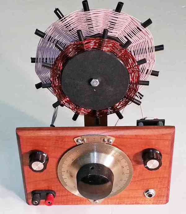
The crystal radio is a timeless learning experience, often our first insight into how a radio works. For some of us that childhood fascination never dies. Take for example Jim Cushman, this guy loves to work on vintage scooters, motorcycles, and especially crystal radios (special thanks to fellow coil-winding enthusiast M. Rosen for providing the link). Digging more deeply we find an entire community devoted to crystal radio design. In this article we will get back to basics and study the fundamentals of radio receiver design.

How it works:

A crystal radio is basically a high Q resonator tied to an antenna and an envelope detector. These days the envelope detector is a point contact diode such as a 1N34 Germanium diode.

cs09-schematic

The resonant circuit passes a specific wavelength (or more specifically range of wavelengths depending on its Q). The diode detector provides the amplitude or envelope of the signal(s) within that wavelength. A high impedance or highly sensitive ear piece converts this envelope to an audible signal that you can listen to.

The neat thing about crystal radios is that no active RF amplification is used. The radio is powered by the incoming radio signal that it is tuned to. More sophisticated crystal sets might have more than one tuned stage, perhaps 3 or 4 to minimize receiver bandwidth for maximum sensitivity and selectivity.

Continue reading “Getting Serious About Crystal Radios”