
Designing parts to fit perfectly together is hard. Whether it’s the coarseness of our fabrication tools or the procedures of the vendor who makes our parts, parts are rarely the exact dimension that we wish they were. Sadly, this is the penalty that we pay by living in a real world: none of our procedures (or even our measurement tools!) are perfect. In a world of imperfect parts, imperfect procedures, and imperfect measurement techniques, how on earth are we supposed to build anything that works? Fortunately, we’re in luck! From the brooding minds of past engineers, comes a suite of design techniques that can combat the imperfections of living in an erroneous world.
A Case Study in Cutting Corners Where It Doesn’t Count
To give us some context, I thought I’d try my hand at these techniques while building a 2-axis gantry to move around the optics for a laser cutter. The catch? I’m nowhere near a real machine shop, so I’m working with a band saw, a chop saw, a micro mill, and a few measuring tools. Nevertheless, good design practices can still make their way out of a handful of manual tools. Now that the gantry is complete, I thought I’d take us on a design tour of how we can “cut corners” whilst designing projects at home–without really making any performance sacrifices.
Precision Over Accuracy Where It Counts
Sometimes nailing down the exact dimension of a component matters less than the difference in dimensions between components. If we’re fabricating these parts ourselves, we need to ensure that our procedure for handling those parts treats them as-close-to-identical as possible. In the case for the laser cutter, the frame becomes a great candidate for ensuring that related parts are nearly the same length.
I’ll admit that the design phase of this project had me drooling over a sweet CAD model once my parts were in place. Extruded tubing modeled to an exact 850.00 millimeters…. corner bracket models that were perfect cubes…. Fabricating 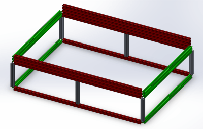 those parts to actually meet the dimensions of their CAD counterparts, though, would be another ordeal. Sadly, all I had to measure my extruded tubes before cutting them was nothing more than a floppy measuring tape. Crude? Yes, but I could get the ballpark dimension that way. Luckily, the secret behind designing a working gantry frame is that meeting the exact dimensions of these tubes doesn’t matter! What matters is achieving tight relative dimensional tolerances across parts that needed to be the same length.
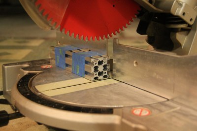
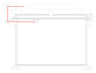
Let’s take an up-close look at the gantry frame. The red lengths are 850 mm; the green, 600 mm; and the red, 160 mm, according to the CAD model. With a measuring tape, I can’t get any better than within a couple millimeters of those dimensions. That’s OK, though. As long as the frame tubes of the same color are all as close as possible to the same length, the overall frame will still be square (…or square enough). How do we ensure tight relative dimensional accuracy? Tape them together and cut them all at the same time!
Accounting for Imperfect Stock Parts
Designing parts to fit perfectly together is hard, but a truly perfect fit is impractical. In fact, engineers don’t even design systems assuming their parts will need a perfect fit. Rather, they’ll design their parts to accommodate a range of dimensions. Engineering has cute word for it: tolerances. Sometimes it’s me: “I can drill that hole to 8 [mm] plus-or-minus 0.1[mm].” Sometimes it’s the datasheet: “Thicknesses are plus-or-minus 0.05[in].” Either way, tolerances give a range to our dimensions. If we keep these tolerances in mind, we can design to accommodate these ranges such that our parts will fit together even if their dimensions are slightly off.
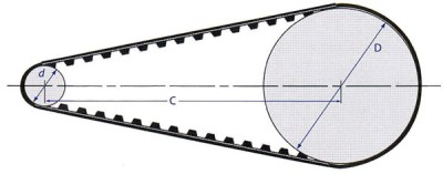
As an example, let’s take a look at a stepper motor driving a shaft through a timing belt and two pulleys. According to the manufacturer, the timing belt has a nominal length, determined by the belt’s tooth pitch and number of teeth. The pulley’s also have a nominal dimension called the “pitch circle,” which is a virtual circle around the teeth where we can assume that the belt rides. Given the dimensions of each pulley’s pitch circle and the nominal length of the belt, we can calculate the spacing between both pulleys.
Unfortunately, timing belt lengths tend to vary with the tension, temperature, and life of the belt, so predicting a belt’s exact length just isn’t practical. Luckily, we don’t need to! By keeping in mind the variability in belt length, we can design our part to accommodate this variability with a range of set points for the connecting parts.
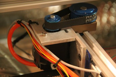
In the case of the laser cutter X-axis, I converted holes to slots around the nominal length of the belt. To tension the belt, I can simply pull the motor down the slot once it’s engaged with the belt. All-in-all, this belt is a little short to assume that it’s going to stretch significantly. On the other hand, the motor slots play a handy second role during installation and removal. To remove the motor, I can slide it down the opposite direction to release the tension. All-in-all, it’s a dead simple modification, but it solves the belt-tension problem without the need for any fancy belt tensioners or additional parts!
Designing for Calibration — and Then Calibrating
When we designed that motor plate, we gave it a nominal length and then added a range above and below to account for belt stretch and other variations. We can take this same idea for a variety of mating parts. Unfortunately, sometimes we can’t find that exact set point where the two parts meet by feel. In those cases, we something better. We need a few more tools and techniques to get everything in the right spot.
 Most CO2 laser cutters these days use a technique called “flying optics.” Despite the fancy name, it’s a pretty straightforward concept. Rather than move the entire laser over the surface where we’d like to cut, keep the laser fixed and just move around the beam. A flying optics setup works wonders since our gantry motors need only be powerful enough to kick around a few bounce mirrors, rather than the entire tube, with reasonable acceleration. The catch? When we first assemble the laser cutter, for all we know, one shot from that laser and we could be blasting a hole off to the side, out of the frame, and into the neighbors yard! (Seriously, let’s be safe about this, folks.) In short, the optical path of the beam needs to be precise with a precision that can’t inherently come from the design. (I’m building this in the garage, remember?) The machines that made our parts aren’t perfect, and neither are our crude hands that screwed those parts together. In a nutshell, we can’t guarantee that parts will fit in the exact spot they need to be for a proper beam path. To build a laser cutter, we need to design for alignment, and then align it! Our fellow laser-cutter-building folk get around these imperfections by mounting their bounce mirrors on platforms that have an adjustable set point with a fine granularity. On my gantry, I installed three of these.
Next comes the actual alignment. Heads up; the laser is invisible! It’s also quite good at burning anything that gets in it’s path. No big deal, right? (Safety glasses on, folks!) For starters, I got a rough estimate of 45 degrees with a protractor and screwed down the mirror plates at that point. From there, I made a rough guess at the path of the beam, put a piece of paper in the way, and–POOF–fired that laser right through the paper! At this point, started tweaking each mirror until the burn marks on paper roughly made their way over to the direction of the mirrors. After a few rounds of poof-and-tweak, I had the laser roughly landing all three mirrors.
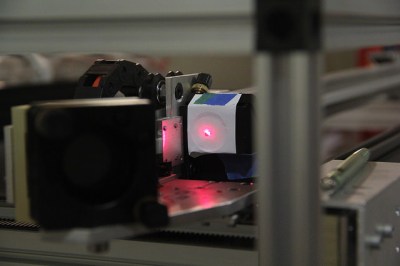 For the last step, I needed a far better guesstimate of the true location of the beam then my truly holey paper was going to tell me. I needed those mirrors at a true 45º, and no measuring tool in my garage was going to get me there. Rather than try to rely on perfect mirror angles, the wonderful folks far wiser than me have suggested spoofing the actual path of the laser with a visible guide laser, so that’s exactly what I did. After putting a few burn marks on paper, I jigged up a laser pointer to trace those burn marks. From there, I could confidently predict the beam path and aligned the mirrors to their final position.
A Journey to Precision with Imprecise Parts
Presto — that’s one working laser cutter from a cluster of aluminum tubes, plates, and a pair of monkey hands to screw them together! Something is strange, however. These parts made on the chop saw and milling machine were, to be fair, pretty ugly. Holes were oversize. Surface finishes on those cuts were an abomination. Despite these imperfect parts, with the proper tools and techniques for alignment, I could still achieve a working system. The accuracy and precision come from not the parts, but the tools and techniques used to finally put them in the right place — making allowances. It’s a lesson learned.
In the real world, nothing’s perfect. Guitar strings must be tuned. Bike brakes must be tensioned. Despite these errors, if we design our parts with calibration in mind, focusing only on the dimensions that matter, we can still tune our system into a working state. To all the folks out there trapped in the real world, we’d love to hear about how you’ve tweaked your designs for tuning in the comments.


When it comes to design, if I had the choice I’d keep imperfect manufacturing if I could have perfect users instead.
Is that the proper blade in that saw to be cutting aluminum extrusions? I heard chop saw, which makes me think a fiber / abrasive blade :/
I use a carbide tooth just like blade like that all the time to cut up to 1/2″ aluminum plate on a table saw. With a tiny bit of oil for lube it makes a beautiful cut. No coolant needed. A heck of a lot more pleasant than any abrasive cut, though hearing protection is mandatory.
I see no reason why it wouldn’t work, but I was just wondering if it’s the best way. I guess as long as you come out with as many digits and limbs as you went in with! It just seems like stuff would want to kick with that course of a blade.
I just got a new table saw, but I’m not sure I’ll be cutting aluminum plate on it any time soon!
I’ve worked with extrusion before, but I adapted my design to work with factory lengths, which at least with the name brand stuff, is pretty exact from go.
I’ve seen recommendations for using a blade with lots of teeth (60-80ish) so best to not use the 16 tooth rip-saw blade that’s normally in the table :-)
I also vaguely remember there was something also about the angle of the tooth ‘hook’ being important (not critical I think) but can’t remember the “whys and wherefores” of it
It’s termed rake, and for cutting metal, it is recommended to use a negative rake. I purchased a saw (damn expensive) specifically for cutting metal with a circular saw. Lots of teeth (60) and a rake angle of about -4 degrees.
Yeah.. the correct blade (high teeth count) and negative rake angle costs nearly as much as the saw you install it on (for hobbyists).
But it’s worth it.
Yeah you cut aluminum with a wood styl carbide blade. It would just clog up a grinding disk
There are specially made saw blades for aluminum, however it is common to use common multi-purpose blades. Usually blades capable of cutting non-ferrous metals have a fillet or chamfer on the profile every other tooth. NOTE Fiberglass does need special abrasive blades. Found that out the hard way.
There are carbide blades rated for cutting aluminum and even steel. A fine toothed wood cutting blade will work ok for most aluminum alloys.
Make very very sure you clamp that aluminum down and cut very slowly. I’ve had aluminum extrusion jump out of a chopsaw and it is not fun. Damage luckily limited to sore fingers and a lovely hole in the wall behind the saw – which I leave there to remind myself.
Indeed, at a previous job we used to cut large cross-sections of aluminum extrusion for chassis builds with a 240V radial arm saw! You clamped the work, and you cut *very* slowly with a tight grip on the saw trolley’s handle!
There are chop saws specifically designed to cut metal with a carbide blade. I got a really good deal on an early model Evolution Rage chop saw. The early ones were really solid. You can get a new Evo Rage with a 14 inch carbide blade from around $200. Much better than abrasive chop saws or small band saws and will even cut steel. They are not great for steel rod. Better for steel tube. With a little more money you can buy a low speed circular saw from Grizzy and others that will take on most anything.
Cutting aluminum with a chop or table saw, no problem. That one I learned from an ancient mechanical engineer who was nearly deaf. He’d crank up the table saw to rough out any old chunk of aluminum before more precise cuts on a mill. It was NOISY, but cut real nice. Of course, he couldn’t see why we complained about the noise. ;)
Of course he couldn’t see with his ears…
Can we get a high-res version of the title image? I need that as my desktop wallpaper!
2nd this
http://waifu2x.udp.jp/
Plug the image url in and select 2x upscale
interesting URL, but that doesn’t produce any higher resolution — it just upsamples it: exactly what you’d get if you use the original image and just tell the wallpaper to fill your screen.
(I assume that’s another Joe Kim piece. Fantastic, as always. If all the work here like this is his, how the heck does he maintain that kind of output?)
Not exactly – that site uses neural network mojo that is far beyond me. The output is definitely superior to per-pixel upsampling.
dahud, seriously?
There’s a technical term for alterations to the original image other than by interpolation: it’s called “noise”.
If that’s to your taste, that’s fine, and this discussion has devolved into an image processing equivalent of an audiophool flamefest, debating which tube sounds “better”.
However, it doesn’t matter: that website produces an almost identical image compared to simple upscaling – just slight sampling artifacts, not attributable to any kind of mojo.
Seriously, save your mouseclicks and save those bits from crossing the pacific a couple of times: (in FF/Win7 at least) just right-click the image, choose “Set as desktop background” and select “stretch” or “fill”, to your taste. Done.
(And I see Joe just posted a huge version. Thanks Joe!)
“However, it doesn’t matter: that website produces an almost identical image compared to simple upscaling”
Did you actually compare?
It’s an algorithm that is designed to upsample drawings by guessing what the lines should look like under the pixelation. Try it – it’s vastly different from just upsampling and applying a bit of sharpen filter.
“Did you actually compare?”
Yes, of course I actually compared.
Plain old bicubic interpolation of the 800×484 “Calibration-02.jpg”, resampled to 1600×968 yields an image very similar to that from that website: Yes, there are subtle differences, on the same scale as resampling artifacts (about 0.5% rms total difference in the image — almost exactly the same as introduced when resampling Joe’s big 3000×1815 version down to 1600×968).
If those differences are to your taste, then you’re welcome to prefer them. I’d consider them noise and objectively a degradation of the image quality, akin to jpeg artifacts (though I’ll concede less visually objectionable).
It might be interesting to see what that site would do to the type of art it’s intended for. Maybe the differences are more dramatic. The demo images they show certainly are.
“and objectively a degradation of the image quality”
The point is not faithful representation of the data in the image, but re-drawing the picture in a larger format, so “objective” doesn’t apply to the case. The point is to minimize pixelated jaggies, blurred lines and jpeg artifacts without causing the typical blotched rounded out “smart blur” effect of typical image manipulation software.
Here’s a link, for anyone who doesn’t want to mess around with this: http://i.imgur.com/73sbp0o.jpg
I had to run the image through twice to get it big enough.
I’ll just leave this here…thanks for the kind words folks
https://www.dropbox.com/s/kear6upqfn3i6v6/Calibration%20big.jpg?dl=0
Joe, your drawings are always amazing!
Thank you very much for illustrating the articles.
They add so much value to HaD blog.
Woot! Thanks Joe for putting up the full-res version.
thanks, 2x with highest noise reduction looks good enough for my eyes.. and I’m keeping that handy!
Great topic.
Other tips:
1. Match drilling: on parts that must have identical hole locations or spacing, clamp the pieces together and drill them all at the same time. Use pilot pins if possible. And importantly also:
2. Acknowledge that your saw fence or drill press table is not (will never be) perfectly square, level or plumb. Drill all holes and make all cuts with the work in the same orientation, so at least the cuts or holes are parallel.
3. Make jigs and cutting guides to hold or guide or position your work.
Fantastic article Josh. Paul adds some great points as well. When cutting/drilling/carving a part, you can’t just look at that one part, you have to look at the big picture and how that part will interact with other parts.
But how do you calibrate it so that the x, y, and z axis are all perpendicular?
As long as you’re willing to make multiple versions you can make precise parts from anything. I made the mech end of my extruder out of wood glue, saw dust, a bit of wood and a few odds and ends from my junk bin. The trick is adjusting every single part until it works.
For example, to get a lever in the right position I pressed it against an old spring and aligned it with tension from a piece of fishing line. It looks pretty ugly, but it works.
Great article :) This could not have come at a better time as I’m in the early stages of building an Open Builds CNC machine.
Thank you!!
This isn’t just for stuff built in a garage. You’ll see a lot of the adjustment features on laser cutters with a half-million dollar price tag as well. Even if you expect the machine to be built perfectly to specs – which is not a good idea even in that price range – you have to expect uneven flooring, rough handling during installation, etc.
adjustment is not calibration
tomato, potato … same thing.
Calibration might involve adjustments, but not necessarily so.
Reminds me, I should write a log for my SECApocalypse project showing how I centered the front end on the frame, and built the fork. Talk about using crude tools to get “good enough” (in this case about 1mm positional and better-than-I-can-measure angular) precision. Along with all said above, welded projects have the fun that welding itself deforms the parts to some extent.
Yeah, I remember one project where I forgot to tack weld before laying a bead. It deformed so much that I couldn’t have welded the opposite side if I tried!
I was always impressed how errors in surveying equipment and their measurements are ‘averaged out’. Take the first reading, then rotate the survey instrument 180 degrees and then also flip the gun/sights 180 degrees as well. Now your error is the same magnitude but inverted. Take a second reading. Then average the two readings to get the correct elevation. I’m not a surveyor by any means, but I I pretty sure that’s what is going on and the terms are pretty close. No need to spend all day taking large numbers of measurements or fiddling with the levels for ever. Just use the built in error averaging in the survey instrument.
Same trick with spirit levels – place on surface, adjust till level, flip round, if the thing no longer reads level snap it in half over your knee, place in bin, buy new one that’s not bent.
Throwing it away? Eh?
You get your screwdriver out and adjust the set screw that affects the levelness of the ‘level gauge’ inside the level.
Flip around, adjust, flip around, adjust.. until it shows the same reading for both orientations.
A level surface is preferable for that, but it works even on slightly skewed surfaces..
And for checking if it is bent or not, look over it’s long side/edge with your eye.. you will see if it’s bent or not very easily.
I generally only fire up my 3d printer when I want to make functional parts. With that said, when I design parts I either account for tolerance and knowing my machine can swing a +- .1mm at slower speeds or .3mm at higher speeds and or layer height, this gives a guideline on the tolerance. Or I design my parts with the intention of post processing. Such as holes being drilled, or reamed to the right size. Some hand filing/sanding. Generally speaking depending on what I need to accomplish I have to account for that in the design. Then again, dealing with plastics, your precision is not as high as it could be in metal. Knowing the material your working with helps a ton. Also on the subject of cutting parts with crude tools. I prefer building jigs that hold the raw material in place, this generally ensures decent accuracy. With that said, always cut longer and adjust via file if necessary.
This is what I do for a living. I’m a toolmaker.
These are good tips, this is how we make things work. Make the shaft smaller, the hole bigger, line up what needs to be lined up. Work with the imperfections you find, and within the limitations of the process you’re using.
Of course that’s what ‘engineering’ is supposed to figure out right? How close everything needs to be made to fit?
Well, in theory, but in practice that’s a great deal of work, and for a small project, or even for an expensive, important project that you’re only going to do once, or one at a time at any rate.
When planning your projects, or designing something, try to build in tolerance in advance. If several parts stack up together, plan on making one of them ‘the size it needs to be make the whole stack the right height’ then make that piece last.
Most importantly, don’t be too clever, don’t try and impress yourself or the world by making all your parts extremely precise. You’re just setting yourself up to be annoyed, frustrated, and the whole thing is going to take more time and more money to complete.
My father, who was a mechanical genius of sorts. Liked to say that the problem with the world was that “There are too many naughts,” as in tolerances like ±.0003″ Too many zeros. Things are cheaper, easier and done sooner when you learn how to make it work with ±.001″ but polish one to fit the other. (ALT 177 is ± btw.)
I do accept as true with all of the concepts you have introduced to your post.
They are really convincing and can certainly work.
Still, the posts are too quick for novices. May just you please lengthen them a little from next time?
Thank you for the post.