If you are a novice electronic constructor, you will become familiar with common electronic components. Resistors, capacitors, transistors, diodes, LEDs, integrated circuits. These are the fodder for countless learning projects, and will light up the breadboards of many a Raspberry Pi or Arduino owner.
There is a glaring omission in that list, the inductor. True, it’s not a component with much application in simple analogue or logic circuits, and it’s also a bit more expensive than other passive components. But this omission creates a knowledge gap with respect to inductors, a tendency for their use to be thought of as something of a black art, and a trepidation surrounding their use in kits and projects.
We think this is a shame, so here follows an introduction to inductors for the inductor novice, an attempt to demystify them and encourage you to look at them afresh if you have always steered clear of them.
Inductor basics
If you consider an electrical conductor with a current flowing through it, Oersted’s Law tells us that current will create a magnetic field around the conductor. If the current flowing through the conductor changes, Lenz’s Law tells us that as it causes the magnetic field to change, that in turn induces a current in the conductor which opposes the current flowing into it. This property is referred to as the inductance.
Inductance is measured in Henries, best described in a straight cut-and-paste from the encyclopedia that you have no requirement to memorise: “The inductance of an electric circuit is one henry when an electric current that is changing at one ampere per second results in an electromotive force of one volt across the inductor“. In practice a henry is a rather large unit, so it is more likely that you will encounter millihenries, microhenries, or even nanohenries.
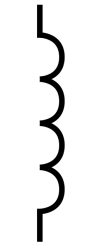
Of course, a single conductor, or piece of wire, doesn’t have much ability to create magnetic field, so doesn’t have much inductance. You can increase the inductance by increasing the length of the conductor, but since you will soon run out of space for very long pieces of wire it is normal for all but the tiniest inductors to have that long length of wire wound in a coil, and round a core made from a material with a higher magnetic permeability than air. Thus the schematic symbol for an inductor is a representation of a coil of wire.
So we’ve dealt with what an inductor is. How about what it does? Where will you use one, and how will it be used?
If you are an electronic experimenter or constructor you are most likely to encounter an inductor in a DC filter, a buck/boost inverter, as a transformer, or if radio is your thing, in a tuned circuit or RF filter. They are not restricted to this selection, but considering these cases should serve to demystify inductors and encourage you to give them another look.
Inductors as DC filters
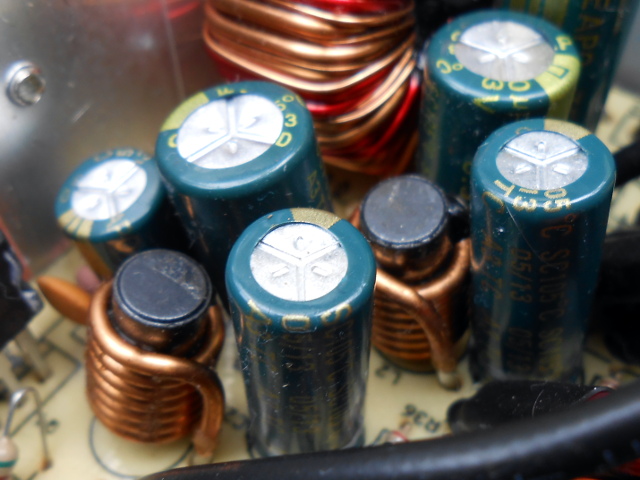
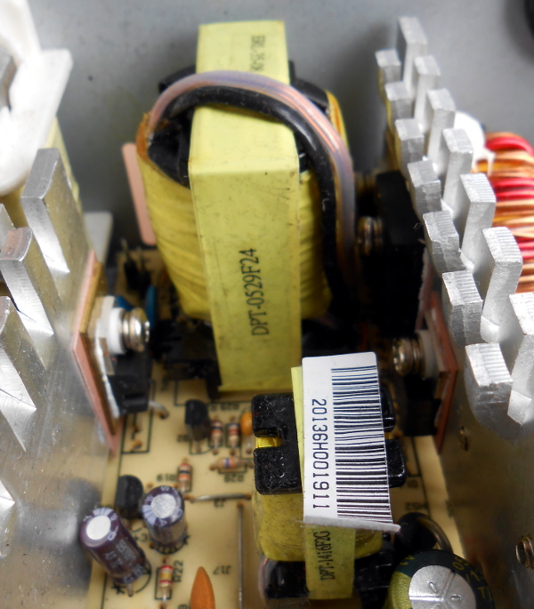
Have you ever opened up a switching power supply, perhaps an ATX model from a PC? Of course you have, you’re a Hackaday reader! If you examined the components, you’ll have noticed a bunch of inductors with coils of thick enamel-covered copper wire next to where the DC cables emerge to power your computer. These serve alongside the smoothing capacitors as a filter, to remove the high frequencies and leave only the DC in the PSU output.
If you remember the paragraph earlier in which we mentioned that a rapidly changing current causes a changing magnetic field which in turn induces an opposing current you may begin to understand the theory of how these filters work: those induced opposing high frequency currents cancel out the input currents responsible for them, meanwhile the stable DC component causes no change in magnetic field and thus no reverse current and passes through unopposed.
Buck and boost inverters
Buck and boost inverters by comparison use the inductor’s ability to store energy as a magnetic field to efficiently convert DC power from one voltage to another. If you pass a current through an inductor you are storing energy in the magnetic field you have created around it, when you stop the current that field collapses and releases its energy by inducing a reverse current in the inductor. This process happens very rapidly so a significant amount of energy can be released in a very short time as a very high voltage spike. Sometimes this spike is a nuisance, for example relay drivers incorporate a diode to safely conduct it away from their transistors, but in a boost converter the inductor is repeatedly pulsed with energy and the resulting spikes diverted through a diode into a reservoir capacitor from which a higher output voltage can be derived.
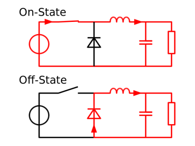
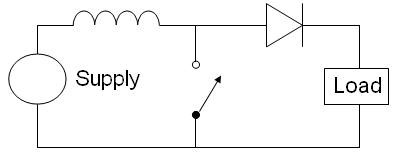
A buck converter by comparison uses the stored energy in an inductor to release a pulse of higher current at lower voltage rather than the high voltage low current spike of the boost converter. The basic circuit is shown on the left, pulses of current create a changing magnetic field in the inductor that induces a reverse voltage which in turn drops the voltage on the load.
Both the example circuits for buck and boost converters shown here are simplified for illustrative purposes. In practice the switch will be replaced by a transistor driven from an oscillator whose pulse width is varied by a feedback circuit connected to the load. This can be a surprisingly simple discrete component circuit, but in both cases there are significant numbers of off-the-shelf integrated circuits designed for the job whose data sheets will provide valuable information about suitable inductor values.
Transformers
If you put a conductor in a changing magnetic field, a current will be induced in it. Lenz’s Law again. This is how dynamos and generators work, and the effect that gives us the reverse current in inductors we’ve been talking about in the last few paragraphs. So if you put one inductor within the changing magnetic field created by another inductor, a current will be induced in the first inductor by that magnetic field. You will have created a transformer, and if we refer to the first inductor as the primary and the second as the secondary the ratio of primary to secondary AC voltage is the same as the ratio between the number of turns of wire in primary and secondary. At a stroke we can change AC voltages from one level to another, and do so while maintaining complete physical isolation between primary and secondary.
Practical transformers are built so that the magnetic fields of the two inductors are as closely coupled as possible. The two coils of wire will occupy the same former and be wound around the same core material, with the aim that all the magnetic flux they create will be contained within that core rather than wasted in the surroundings. The designers of a transformer will have to contend with losses due to induced currents in the core as well as losses due to the resistance of the wire, both producing heat, and with the possibility of the core saturating with magnetic field and the device becoming non-linear at the frequency of operation.
At lower frequencies such as those used by mains electricity the core usually takes the form of iron laminations insulated from their neighbours to reduce induced currents. As the frequency of operation rises the size of core required to avoid magnetic saturation decreases so there is a corresponding decrease in transformer size. This effect is offset by the requirement for higher performance core materials to work at higher frequencies, and for this reason you will see cores made from ferromagnetic ceramics known as ferrites in the high frequency transformers found in switch-mode power supplies or RF applications.
There is another type of transformer you may encounter, the autotransformer. Typically these are used in the inexpensive mains step-up or step-down transformers you can buy over the counter should you wish to use a European 230v appliance on the USA’s 110v, or vice versa. An autotransformer does not have separate windings, instead it has one winding with a third connection somewhere in the middle. Apply an AC voltage between the bottom of the winding and this third connection, and it will induce a voltage at the top of the windings proportional to the ratio between the number of turns up to the third connection, and the whole number of turns. Its operation is very similar to a conventional transformer, however it does not provide a physical isolation between primary and secondary and therefore does not offer isolation from a mains supply.
Inductors in RF circuits
Probably the area of most mystique about inductors surrounds their use in RF circuits. People tempted to try building a radio project balk at the idea of winding their own inductors, and the subject of their design may be responsible for most of that black art we mentioned earlier.
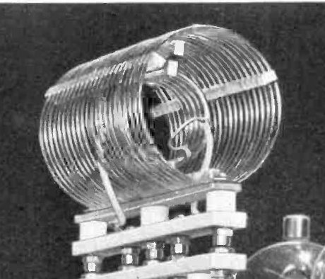
In an RF circuit the designer is most interested in the resonant frequency of a circuit containing inductance and capacitance. In very simple terms if you connect a capacitor and an inductor in parallel and apply a pulse of current to the circuit the energy will “bounce” between magnetic field in the inductor through electric current in the connecting wires to charge stored in the capacitor and back again until resistance losses cause the energy to dissipate, and will do so at a frequency dependent on the inductance and capacitance involved. There is a straightforward formula to calculate resonance that every radio amateur will recite parrot-fashion: “F equals one over two Pi root L C”, but happily there are numerous online resonance calculators if you would prefer to save a little effort.
There is perhaps less need than there might once have been for trepidation at RF inductor design, and in particular at the idea of winding your own inductors. Practical RF inductors in preset values are available off-the-shelf from multiple manufacturers, along with adjustable inductors with threaded ferrite cores that can be moved within the body of the inductor. These components are not as cheap as their resistor and capacitor counterparts, but they do make the RF constructor’s life significantly easier.
Go Forth And Solder
We hope that if you are an inductor novice this article will have given you a basic grounding in the subject and demystified these components for you. As always, there is no substitute for hands-on experience though, so if your curiosity has been aroused on the subject then we’d suggest you get to know the subject by building a few inductor circuits. Start with a simple buck or boost converter based around an off-the-shelf IC, and have a poke around at the voltages and waveforms involved with your oscilloscope. There is a whole world of magnetic goodness out there to be found!


I recall when magnetic amplifiers colloquially known as mag amps and saturable reactors were common components in military and industrial electronics. Heavy things, they left avionics as soon as alternatives were available.
Saturable Core Reactor is probably one of the coolest named components in vintage electronics. Some early Tektronix scopes (like my 555) used one for filament voltage regulation. Surprise, surprise, the whole scope is over 110 lbs!
Still used on simple ATX supplies for the 3.3V rail, right?
They get a lot smaller and lighter at switching supply frequencies.
One of the things I found interesting about working with an Atari 2600 is how many inductors it has. There’s even a variable inductor used to adjust the audio volume. I don’t think I’ve built a single circuit that required an inductor since I picked up electronics.
Are you sure that isn’t just a wirewound resistor volume control? There are volume controls that are autotransformers used in PA (public address) systems, but they are relatively large and are completely unnecessary in something like an Atari 2600. And a LOT more expensive than a resistive volume control.
Yeah, I was wondering about that. Seems very odd, but the schematic shows five inductors in total, including a variable one associated with the audio signal components. I’ve never seen a unit IRL (yeah, I know, a deficiency), but that component doesn’t look user-accessible, and I can’t figure out what it’s supposed to do.
Oh, yeah, there is no speaker in the Atari 2600, it uses the TV audio. That is part of the modulator circuit. Not a volume control.
To me it looks like the adjustable inductor is part tuneable oscillator that modulates (FM) the audio up to the baseband audio sub-carrier frequency.
I just looked at the schematic – much weirdness there!
The instructor is a trimmer rather than a volume control and looks like it’s part of a filter.
But what really got my attention was the two common emitter mode current mirrored transistors configured as an adjustable multi-vibrator with a crystal coupling one phase.
Probably to modulate the audio into the RF antenna input of your TV which I assume was your screen…
Spot on. I had another look and that’s what it looks like to me.
Most importantly, how to measure the inductance of an unknown inductor:
http://youtu.be/CKiQwzH4n-E
I find it much simpler just to use a cheap LCR meter.
But then you don’t get the ability to select your test frequency (well you might, but your choices are limited). That’s the nice thing about using a function gen and a scope to calculate inductance, it’s not hard to do and you can select the exact frequency for the test. Which will yield more accurate results for your application.
Grid (Gate) Dip Oscillators were the tool of choice for RF inductor work back in the day
Excellent intro.
But fscking ferrites. How do they work? In particular, the black art of how to choose a particular ferrite for frequency, saturation, etc. Is that out of scope for a HaD article?
And to DV82XL’s comment: how about a HaD on mag amps? Pulse forming networks? Fluxgate magnetometers? Voltage regulating ferroresonant transformers?
And while we’re on ferrites, how about microwave circulators or isolators? They are high weirdness indeed.
That would be great!
Just going by the recommended circuits can’t be the best way to choosing the (a?) right ferrite.
Damnit! I had a good cite for ferrite/toroid core choice and then I lost it. The short version, though, was get the datasheets of a bunch from Mouser (or distributor of your choice) and then pick ones that work at your chosen frequencies.
There was a rant in the article against the Fairite 42 or 73 or some other ham favorite that worked perfectly well 40 years ago, but is now expensive and superceded. Anyone know what I’m talking about?
I assume the header image is another [Joe Kim]? Quite nice, once again! I’d love it if high-res versions of all these headers were made available, like he did for the “Good Enough!” slide rule a few days ago. Would that be doable?
Yes, I love this one and it is indeed Joe Kim’s work. I also want to see his art made available for everyone. We’re still working on a method of doing that automatically and I’ll make sure to keep pushing the effort to get it done. Thanks!
+1 to that! :)
Well written article! Very informative.
Am I less of a ham because I don’t have that formula memorized? ;)
We both are :P
It’s about the only formula this G7 has memorised :)
I was a real wiz at these formulas. People would ask me if they should use the left hand or the right hand rule and I would say – Well! are you left handed or right handed … anyway if the inductor doesn’t work the way you expected then just take it out and put it back in the other way around.
As another ham I don’t judge anyone on the formulas they do or don’t have memorized including Ohm’s law. Records of the formulas are easily referenced when needed. I have kept my textbooks and I just ask Siri if my textbooks aren’t at hand.What’s important to remember is that there is a formula and when it would be applicable.
If we go with “what is inductance” instead of the above mentioned “This property is referred to as the inductance” one needs to go to Maxwell’s 2 ” A Treatise On Electricity and Magnetism” Volume 2, where in chapter VII “Theory of Electric Circuits”, the dynamic understanding of [self induction](1) and [mutual induction](2) are defined as terms that substitute the terms defined via the notations from the theory of dynamical forces: [electric product (of the moment) of inertia](2) for the letter and [electric moment of inertia](1) for the former. If one goes even earlier, one will find that Faraday’s term of “induction” has very little to do with with how induction is described in the article. It seems like using “induction” is something that we have to think twice before talking about, especially if one goes and researches the fundamental works that allow these terms to propagate to the current times.
Uuurrrk. Bad memories.
Back in the 80’s I had a “Ferris Bueller” style teacher who told us “The slope of a line is the GRADIENT”. My eyes rolled back…
…and when I woke up, the board was covered with Div, Grad, Curl and directional derivatives. The teacher was saying “You will need this, to understand Maxwell’s Equations next week”.
That’s when I knew I was screwed.
Thanks for the article
Informative article.
You have an error there in the first paragraph, 2nd last sentence: a VOLTAGE is induced, not a current. (E = L*di/dt)
I like analogies, and the water analogy to electricity is a time-tested good-one. Water flow rate ~ current, water pressure ~ voltage. A resistor is just a constriction in a water pipe, and a capacitor is a piston in a pipe attached to given point with a spring (pressure on one side of the piston displaces it, storing energy in the spring)
Inductors can be modeled as turbines in pipes with mass, where mass ~ inductance. The fundamental law, E = L*di/dt states that the voltage (pressure) is equal to the rate of change of current times the inductance. Or, that the change in current in a circuit is limited by the inductance and the voltage across the inductor. When we apply a step pressure change to a turbine, the water flow (current) does not increase as a step. Rather, it gradually spins up the turbine, the water flow through it increasing asymptotically to a steady state determined by the resistance of the circuit (sound familiar?). If you try to stop current flow abruptly (such as when you open a switch, the momentum of the turbine will prevent it from stopping spinning instantaneously, and a massive pressure (voltage) will develop across it.
Nice analogy! I like that one, and in 30+ years in electronics, I’ve never heard it.
That analogy made inductors MUCH clearer to me than the article did. Thank you.
I always thought of inductance simply as the momentum of the ‘water’, which seems to fit nicely with the coiled pipe idea–more water, more mass, greater momentum, and technically all wires have a small amount of inductance. The turbine is a good analogy for an added core.
The turbine allows you to analogize coupling between inductors. Transformer ratios just become gear/pulley ratios, and just like an actual transformer, the impedance on one side of the water transformer can be mapped to the other side by the gear (turns) ratio.
Very well made article
Your formula for an lc parallel circuit is wrong.
Should be f= 1 over 2 pie divided by the square root of LC.
73
de WZ2Z
Yeah the article was good but a bit light on formulas. Some basics –
R Resistance Ohms
L Inductance Henries
C Capacitance Farads
f Frequency Hz
Capacitive Reactance: Xc Ohms = 1 / (2 π f C)
Inductive Reactance: Xl Ohms = 2 π f L
Series or Parallel resonant frequency: f Hz = 1 / (2 π √(L C))
Q Factor (Series RLC): Q Ratio = (1 / R) √(LC)
Q Factor (Parallel RLC): Q Ratio = R √(C/L)
RC Corner frequency / 3dB / half power frequency: fc Hz = 1 / (2 π R C)
RL Corner frequency: fc Hz = R / (2 π L)
RC time constant: t = R C (time to increase charge by 63.2 %)
At the risk of sounding far to post a propose a question. Is the a daily identifiable marking or mode of composition when replacing failed inductors in a circuit? For example I had a router that would not post, and once opened the hardware was making an audible tonethat had resonance in the upper ranges of human hearing. I was able to trace this tone to the inductor which had overheated and seeped the entirety of its “glue stuff that insulates the wire” onto the board. The tone could be attenuated (under power off course) via the physical pressure applied to the coil how would I go about knowing what to replace it with?
The inductor is probably fine. The real problem is most likely dried out capacitors.
So is it possible dry cap caused the insulating (glue?) to melt and the tinny noise on power? If so, should I just check the cap for continuity or replace all the suckers?
The inductor may need re-gluing but the original cause is most likely dried out capacitors. Apart from initial power up the intention is that the inductor has mostly AC across it and perhaps a little DC depending on the switching mode. This achieved by having the next filter capacitor storing the peak voltage and slowly releasing it. When the cap dries out then the inductor is carrying the DC load and the DC resistance of the coil causes the heat – inductors are not perfect.
So if it’s a bog standard SMPSU where the inductor is series between filter capacitors on a DC power rail then yes check the caps either side. In any case check caps they’re the most common failure cause – the usual dead ones are the high value electros in the higher current paths of the output DC rails (filter caps) and any small 1uF electros on the primary (regulation) side. Replacements should be 105 degrees Celsius of the type (Low) ESR. You probably won’t find ESR for higher values so use TKR there.
Also check that there are no shorts between turns on the inductor and that the enamel isn’t burnt off. If it’s faulty then jump on ebay for some wire of the correct gauge. The ferrite will be fine. It’s highly unlikely that there is a fault with the coil itself.
The tool you want if you often fix SMPSUs or anywhere your replacing elecro’s is called an ESR meter or a Low Ohm Meter and is often bundled with a RLC meter as a all in one. They will measure CAPs in circuit. They’re on ebay to.
I’d have to see a picture, but I doubt you saw melted insulation. If it were, it would short out a winding and not work. More likely that is just the glue they use to stick down the ferrite to the board so it doesn’t vibrate in shipment and break a wire.
I concur with others that it is more likely dried out electrolytic capacitors causing high peak currents causing the noise.
I have mostly inductors them for band passes in my home brewing career both for audio and radio. The coolest was a few hours before a good high ISS pass realizing that I had no antenna duplexer(or antenna) for a ham radio satcom rig for my old real two band one VHF one UHF DJ-580 HT transceiver. It involved wrapping some wire from a sacrificed cat5 cable around a pencil for a few wraps to make inductors fo the low pass, the high pass was a few ceramic caps though I almost had to make them with foil and tape when I found some that added up to the right uF in some junked electronics. It worked and we were able to talk to the ISS and a later AO-27 pass so all good though the dual band 7 element 70cm UHF/4 element 2m VHF jpoles and yaggi antenna fell apart pretty fast. Think Gilligan’s island or Lost improvised bamboo and stripped down cat5 for both antenna and the duplexer and transmission line tacked onto a thicker bit of try bamboo. I also had an old Zaurus SL-5500 running petittrack for calculating the pass and doppler shift zip-tied to the shaft.
Probably a good article to add an op amp gyrator circuit description.
I realize that reliability characteristics and failure modes are rarely identified on this site, but it would be a good idea to familiarize yourselves with thermal aging of inductors, the different types of core materials and their characteristics, the UL insulation classes and de-rated temperature ratings for inductors.
Then again… did I just see an article about replacing a noisy fan with a quiet one? Sort of like LifeHacker.com’s article on adding a slight amount of water to an almost empty sriracha bottle so that you can use all of it up before recycling the bottle?
Fewer articles with more depth is a good thing.
Not that I’m saying no one shouldn’t familiarize themselves with what you suggested they should, but I have to question to what end? Good advise if your plan is to manufacture items for sale. The typical DIYer is well served if they purchase components that have specifications that match the parameters within their project
A follow up article to this might be benefit from taking a murata or coil craft datasheet and explaining what each parameter means, which ones you need to focus on for filter circuits, power supply circuits, RF circuits, etc.
Same thing with any other component article.
I think each of these sections need it’s own 10 part article.
No mention of air gaps to control saturation, no mention that the energy storage of an inductor happens almost entirely in the air gap. Permeability and flux mentioned in passing. Nothing about flux loops, Hard/soft magnetic cores, magnetisation curves. Word electromagnet not mentioned once in an “everything about coils of wire article”.
What’s in the article isn’t bad, but I think it was a mistake to try cover such a wide topic. It might be most of what someone would want to know casually, but people are going to need to know a vast amount more before they actually go forth and solder. Just building a buck regulator with an off the shelf driver that *works* is going to take most people down a deep warren with alien physics where every wrong hole has a landmine filled with magic smoke.
You are asking Hackaday to publish a book in an article.
I see nothing wrong with posting this as an introduction to inductors. You have to start somewhere. Do you propose that newBs get inundated with a soul-cringing amount of information for their first intro to coils?
The answer to that question is how much smoke do they have to release?
You know what’s really missing from the buck and boost regulators shown above? The friggin waveforms.
Someone went and did this for you:
Here it is:
http://www.ti.com/lit/sg/sluw001e/sluw001e.pdf
It’s better than the wikipedia drawings.
You know what’s missing from the TI paper? References for when to use a shielded inductor vs non-shielded. The thermal dependency of inductance. The positive feedback loop for thermal runaway in a control system. That last part is the reason why thermal aging happens and keeps on getting worse.
Then the types materials that prevent this from happening. That would cover key performance charactersitics, the losses in switching inductors (eddy current, hysteretic and I2R copper,) the characteristics of the materials that can make up the cores (sendust, ferrite, etc.)
In fact, maybe a new, large dedicated article just on the failure modes, and reliability of components would be good for newbs.
Just cause it works on your desk… doesn’t mean its going to last.
I agree. Much of what people are missing from their knowledge has to do with durability and robustness. Like someone building a car without caster, camber, or toe-in on the front wheels.
Are yo saying it’s OK to ignore the Akerman geometry and anti-dive characteristics into the front suspension of a car? :)
Thermal aging! This sounds like a great recipe for Timed Life in all sorts of power supplies. Cook up the right mix of ferite and this device will self destruct in… It’s bad enough with caps and their brown goo getting out. Caps easy to fix, but the inductor…recycle time.
Throughout this article, it keeps referring to the changing magnetic field or changing current through the inductor (they’re the same up to a scaling factor) inducing an opposing current. The changing field/current induces an opposing VOLTAGE, not current. V = L di/dt. This is self evident in that you can measure the voltage on an open-circuited transformer secondary (e.g., voltage without current)
I see a lot of this now.
Great article!!! Lots of good information! Thanks Jenny!
Respectfully the tutorial in mt opinion left out some important details. The first being for inductance to be present there has to be apparent movement between a conductor and a magnetic field. That move can be created by mechanical means or passing an AC current through a conductor.. True a straight length of wire can act as an inductor. Perhaps it because how I’m perceiving things at the moment, But Jenny’s description read like the reason conductor take on a coil form is to be able to fit more wire into smaller space. That would have beenthe opportunity to p[point out that the number of turns of wire in inductor play a factor in the inductance exhibited by an inductor. In the even that was mentioned elsewhere in the article I missed it. Today I’m operating with an older pair of eyeglasses that tends to messes me up in so many ways, so I’m unsure if I’m making sense.