[Derryn Harvie] from the MakeHackVoid maker space hacked a $10 IR Thermometer and made it talk USB. Sounds easy? Read on.
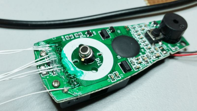
He opened it up in the hope of finding, and tapping into, a serial bus. But he couldn’t find one, and the main controller was a COB blob – hidden under unmarked black epoxy. Normally this is a dead-end. (We’ve seen some interesting approaches to decapping epoxy blobs, and even ICs with lasers.)
But [Derryn] went his own way – intercepting the data going from the micro-controller to the LCD display, and reverse engineering it using another microcontroller. He scraped off the solder mask over the tracks leading to the LCD display, and used an oscilloscope to identify the common drive lines. He then used a function generator to excite each of the LCD common lines and the segments lines to build a complete matrix identifying all the combinations that drove the segments. With all the information decoded, wires were soldered so he could hook up an Arduino, and the cut tracks repaired.
Since the LCD was a multiplexed display, the bias voltages were at four levels. Luckily, he could extract most of the LCD information by reading just eight of the segment drive lines, using up all of the analog inputs on the Arduino. Perhaps a different microcontroller with more ADC inputs would have allowed him to display more LCD functions. Well, he can always upgrade his upgrade later. If you have a similar hack to implement, then [Derryn]’s code could be useful to get started.
Thanks, [csirac2] for sending us this tip from MakeHackVoid.


Nice. That’s impressively determined work, there. Do you think it would’ve been easier or harder to grab the signals between the sensor and the epoxy blob instead, and correlate those with the displayed values?
I would have tried that myself first. There’s a fair chance it’s a Melexis IR sensor or clone thereof.
Nice I have one of those IR guns for RC stuff don’t do RC anymore comes in hand for Pies and Steak though.
Can’t you put a camera on the readout, then OCR the resulting snapshot, and get results that way?
Michael
There are countless articles on dong that with power meters, so yes it’s possible, but it isn’t a nice solution for a thing you want to be mobile.
If only there were a very large but coarse visual sensor you could stick straight on such displays.
I wonder if there is something that could work like that. something you could hack to be a coarse light-sensitive array.
Maybe that old trick where they use LED as detectors instead of emitters, and then use some LED strip of sorts and stick that on it. (Using a commercial variant of a photo array would be cost-prohibitive I imagine.)
I just have a feeling there is a simple solution I’m not thinking of at the moment.
I’m talking in general for all devices with LCD displays BTW.
The real hakers are back…
Agreed. This arduino/raspberry pi shit is really getting old.
“So I went about reverse engineering the LCD drive, and reading it off using an Arduino”
Arduino shit you say ?
+1 ! LMAO, good comment. ????
+1000 this hack is the kind of thing that got me reading HaD back in the day! More like this!!!
I had a multimeter with an IR data port on it … Writing to it was easy, simple serial commands, reading from it was another story
After hours it turned out the way it read it was serializing the lcd segments not just giving me data
Interesting to say the least
Might me doing what he did here on top of a standard multimeter chipset
It seems he jumped straight to a MiTM hack on the LCD, why? I would first look at the sensor which is almost guaranteed to have either an analog or serial data interface.
No idea but sometimes sensors need a complex set of manipulations to get usable data though (amplification and correction and such). But often enough it’s dead simple too as you say.
Hundreds of projects to encode to a HD48770.
A library to hook up to an existing one and decode it would be pretty awesome.
And yes I’m aware of the difficulties in doing that, which is why I’ve likely not found one yet!
Yes, I’ve been considering something to do just that.
I think I’m close to having it working (on paper anyway). I’ll see if I can get it going this weekend.
most of the IR thermometers I’ve seen use a Melixis sensor
You can buy a Infrared Thermopile Sensor, like the TMP006 or TMP007 from Texas Instruments (4,10 € by Mouser), if you want to measure Temperatures from –40°C to +125°C.
With a Micro-controller you can read out the date over I2C and send this to a Display or a send it over a USB-Connection to the PC.
This is much less work then the read out of the LCD-Connection.
Good advise, and nice that you give the part numbers and ballpark price.
And I see adafruit has support for it too https://learn.adafruit.com/adafruit-tmp007-sensor-breakout/overview
Including a downloadable library.
Addendum: It’s interesting though to be able to read out ANY device with LCD, and so for a HaD article this is better than “get a ready-made sensor, done”.
Nice hack, albeit tied to the specific brand and model of the thermometer as others could change their way to talk to the display. The sensor, though, should be pretty common; probably a Melexis MLX90614 or a similar one in the same family. In that case, the sensor outputs the read data on a SMBus interface, so tapping the serial channel and possibly streaming the data using radio modules becomes feasible.
Data sheet here:
http://www.melexis.com/Infrared-Thermometer-Sensors/Infrared-Thermometer-Sensors/MLX90614-615.aspx
exactly, I needed at least 16 IR thermometers for a system to help stop 1 day old turkeys from “crushing”, they pile up in the corners of the enclosure, 10 – 20 deep and suffocate.
@$30 each (https://littlebirdelectronics.com.au/collections/temperature/products/infrared-thermometer-mlx90614) the Melexis sensors were a bit expensive, I found some cheaper, ready made units for $15.
I bought one, took it apart, saw the part number and just went with the Arduino library.
The 2 test units worked pretty well, getting woken up at 3am by a beeping alarm was way worth it when it saved hundreds of young turkey lives
Just brainstorming here. How about this idea? May be a little labor-intensive but only once. You can get your brother-in-law to do the screen-caps mock temperatures and save them to your laptop (for a beer or a coupla’ quid?) :-) http://oi68.tinypic.com/1jq35l.jpg
If you just wanted to probe the temp, you could have just tapped the lcd with an eeprom, or even just a generic decoder/encoder ic- and it would require no reverse engineering or risky depotting…The alternative is to just process the feedback to the photosensor directly and ignore the oem circuit at high enough sample rate. If he didn’t have way to get the moicrocontroller to sample fast enough, it would have been super easy to just tune a voltage multiplier to the frequency and derivative of the function of temperature to pulsewidth… This project is unnecessarily complex. It should have taken about an hour for someone at his skill level…
Even I did the same thing to grab temperature from thermal gun. And figured out around 7 pins manipulating 4 seven segment display on screen but couldn’t figured out how you are using Arduino to grab that voltage levels(3v,2v,1v,0) which are varying continuously at frequency around 100hz. It would be helpful if you explain code with proper comments which was there in following link.
https://forum.makehackvoid.com/t/reverse-engineering-a-ir-thermometer-lcd/724/17
I have a device gm320 infrared thermometer and I want to receive the temperature read on the LCD with an Arduino and transfer it to HMI through Modbus.
Is it an MLX90614 sensor?
Thank you if you help me.
Qashqaei