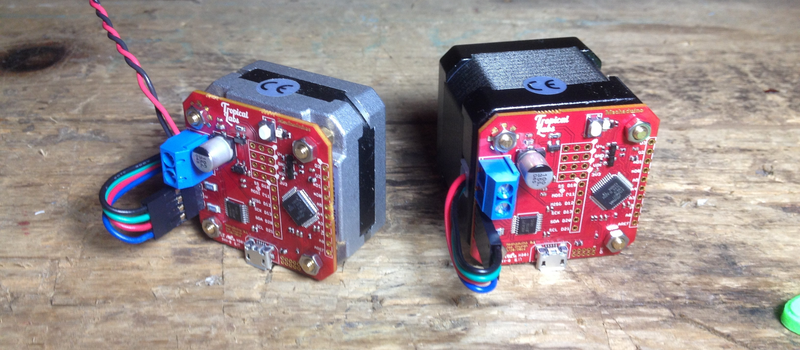
Is it something in the water, or have there been a lot of really cool servo projects lately? Mechaduino is a board that sits on a regular stepper motor and turns it into a servo with a closed loop control of 0.1degree.
Whenever we post something about using cheap brushless motors for precision control, someone comments that a stepper is just a brushless motor with a lot of poles, why not just control it like one. That’s exactly what the Mechaduino does. They also hint at doing something very clever with a magnetic encoder on the board which allows them, after a calibration routine, to get the accuracy they’ve promised.
T
he Arduino-sounding bit of the name comes from their full compatibility with the Arduino development environment. The brains of the board is the compatible, SAMD21 ARM M0+ chip. They wanted the board to be as accessible as possible. On top of this, it also allows the user to use any control algorithm they want for the board. Most industrial controllers are limited to PID control, for returning to the last sent position. Opening up the control allows for interesting applications, such as motors that behave like mass spring damper systems, or electronically gearing the input of one stepper to the output of another.
The board supports lots of standard communication protocols, but the acceptance of regular stepper inputs make it extra interesting. It can become a drop-in replacement for the motors on a normal CNC or 3D printer, which have full closed loop control as shown in the video after the break.
They intend to keep working on the project until it gets to a level where they could kickstart it. However, rather than vaguely promise an open source release sometime after the launch like some have done, interested readers can skim all the design files off their GitHub and get to playing with it today. Firmware and Hardware.


for sale when? i have a CNC mill (diy) i want to get closed loop
Use a toothed belt based even numbered reduction ratio, and always run in half-step mode (70% motor holding torque).
Why?
Micro-stepping usually means severe torque loss (think 7% drive capacity in 1/16 step mode), and or missed positions at low speeds. This feedback system seems like a ridiculous solution to a problem created by incorrect use of the driver chips in the first place.
A large stepper with a belt reduction ratio is very reliable for CNC mill work, tuning EMC2 is easy, and the run-out will be larger than the jog errors. The better servo systems are almost always proprietary, and in 5 years the company that made them often will no longer sell the replacement parts. i.e. the machine is now the worlds biggest paper weight, and you will never find time to rebuild it from scratch.
I like the idea of an open source hardware independent servo controller design, but have rebuilt enough systems to know that simple stepper drive systems will outlast the operator. Note, one can currently buy large CNC servos for around $300 each, but the make/model/software will always be changing.
=)
“A large stepper with a belt reduction ratio is very reliable for CNC mill work”
Only when the position feedback device is on the moving part. Having an encoder on the motor and using a belt drive is a bad solution for CNC machines that require high accuracy.
The toothed belts are rather popular even for servo drives on old knee mill retrofits. As things start to wear out, people appreciate the ease of maintenance… rather than something needing a broach etc.
If there is a feed-problem on a large machine, than a mechanical fuse in the drive line can reduce strain. Note, people who do climb milling on an older machine don’t know piss about precision anyway.
;-)
I’ve only seen small hobby mills from Taig or Sherline get away with dual diaphragm shaft couplers.
“Having an encoder on the motor” is not really useful for absolute position feedback.
A real DRO is usually based on another piece of sensor hardware bolted into the side of the bed.
=)
I agree with everything here, the problem for me arises when I find out after hours of CNCing, that I missed steps because the machine needed fresh lube. Or when I decide to push it and cut some titanium, the gantry flexes too much. I run 1/4 microstepping, geared down with belts, even, it’s great when tuned and lubed, 200in/min. My weak point if my z-xis, 70in/min tops and doesn’t like drilling down fast without spiraling in – but sometimes, I need 1/8″ holes, and can’t spiral in.
“Micro-stepping usually means severe torque loss”
Wrong. Torque of a stepper motor is entirely independent from the microstepping setting. In fact, currents flowing through motor coils are identical after one full step vs. after 16 microsteps at 1/16.
Exception is halfstepping, which can use a trick to increase torque by 40% at the cost of 100% more current and motor warming.
Current and torque are not directly related when micro-stepping. There is always a loss in stall (and running) torque when micro-stepping. Half stepping Is the one exception.
No Traumflug, you are wrong. Micro-stepping always results in a loss of stall and running torque as Larry said, unless you increase the current to compensate.
Clearly you two don’t know how microstepping works. Simply look at the data sheet of a microstepping stepper driver, the solution is inside there.
Well said Brad.
I think you are not talking about the same torque rating for the motor.
Incremental torque vs. maximum obtainable torque (at same current)
In full-step mode the maximum torque is achieved when there is a 90degree difference in the electrical angle between stator and rotor (so for a 400 step motor that would be 1.8 mechanical degrees).
When micro-stepping you simply allow the electrical field to rotate with less quantisation. At 1.8 mechanical degrees you will have the same torque as with full stepping, but with ex. 1/16 micro-stepping 1.8 mechanical degrees is no longer 1 step, but 16. So the incremental torque pr. step is much less than in full stepping mode.
If the torque profile is not exactly sinusiodal, you may however lose some torque at specific points, so moving 5 micro-steps will not guarantee you to move 5/16 full step.
Use microstepping to reduce the motor “music”, not to gain increased accuracy.
This talks about accuracy loss (there is a nice plot): http://www.ni.com/product-documentation/10638/en/
This talks about how to calculate the INCREMENTAL torque (but the torque before skipping steps will be the same):
http://www.micromo.com/microstepping-myths-and-realities
I was talking about torque with and without micro-stepping while maintaining the same current.
The paper from micromo that Skrogh mentions sums this up nicely. On the mechaduino, we maintain a constant phase advance of 90 electrical degrees to ensure we are always operating with the highest incremental torque for the applied current (and current level is controlled by PID or other control agorithm…)
We use the motor like a BLDC instead of a stepper: We commutate based on encoder angle instead of stepping trough a microstep table. So even when we are positioning “sub step” we have the full holding torque of the motor (minus the detent torque), and if that torque is exceeded, the motor will fight back since it is closed loop.
This is my idea of an open source hardware independent servo controller. https://github.com/rene-dev/stmbl
If you make an early adopter version i know i would get in for a few sets. I got a mill that needs this so badly. If it could also use a linear encoder like from a DRO then i will be forever in your debt. Good luck with that kickstarter.
You cant just use a linear encoder for your primary feedback, that has to be done on a second servo loop. I have tried using linear encoders as the primary feedback a few times and all it does is make it almost impossible to tune and when you do it is very sluggish because any lost motion in between the motor and linear encoder will kill you.
Dynomotion’s kflop is a motion controller that will handle a linear encoder for secondary feedback and it is pretty cheap.
does “closed-loop” in this case *also* take into account the other axes…? E.G. if say one motor loses steps at a specific position every time (due to overloading), will the other motors slow to compensate? Probably not as much a problem for 3D-printing as, say, for CNC-milling where attempting to cut too much material at once would slow a motor… But then, what in 3D-printing would cause missed-steps besides an underpowered motor?
“Keep yo’ hands out mah print-job!”
Really, the way it should work if if your follow error exceeds a set amount the machine just stops, thats how CNC machines usually work.
The better closed loop systems do watch for following error of the entire system as macona says. It seems there’s hints of this system doing that but I need to go read up on it more.
As for why on 3D printing, for desktop a well-tuned stepper is fine but you get into larger formats or even just long print times, then there is a desire for something that can handle upsets. Some systems can vary the current input to demand, so you’re not running the motor hot so much, and it can take higher peak currents on occasion if that’s true.
I was browsing IO a few hours ago and bumped into this one. I wondered why there wasn’t a post about it..
This is really cool, and what they achieved so far looks very promising,
Looks great, and I would buy a few of then if ready, but couldn’t the as5047d be replaced? With taxes would be around 20 dollars just this one for me in Brazil….
Thanks for the write up Gerrit!
Small correction: we have a resolution of closer to 0.022 degrees (14 bit encoder).
For those interested in getting their hands on the hardware, follow our hackaday.io project and we will make an announcement when it is available!
https://hackaday.io/project/11224-mechaduino
-Joe
Isn’t this exactly whatwas on Kickstarter a while back as ‘uStepper’?
Joe here, designer of the Mechaduino. I recently saw the ustepper kickstarter, and I can’t find any demonstration of their motor running in a true closed loop mode. I believe they use an atmega328 processor… we had to move to the more powerful SAMD21 processor to run the control and commutation algorithms.
Check out our demos of the Mechaduino doing stuff!:
https://www.youtube.com/channel/UCGg_1plkRDMVlN1Q_DBpB8Q
I for one am excited to see this move forward! I’ve always wanted to put a closed loop system on my existing system (combo of nema 23 & 34 steppers) that’s been operating for quite some time. And as it’s a hobby system, simply pulling and retrofitting for servo’s just won’t happen.
Thanks for the write up Gerrit!
Small correction: the resolution is closer to 0.022 degrees (14 bit encoder).
For those interested in getting their hands on the hardware as soon as possible, please follow our hackaday.io project. We will post an update as soon as they are available.
Will you be making them for NEMA 34 motors with 1600 oz-in torque?
You can put the Mechaduino board on the back of any bipolar stepper motor (provided you can place a small magnet on the rear of the motor shaft for the encoder). The only limitation is the phase current limit of the on board H bridges (2 Amps each), but we are thinking about creating a higher current H bridge daughterboard/shield for higher powered motors.
Hi, do you still plan to build a board that can hold higher current for NEMA23 motors ?
If you really mean “open source”, then how about using KiCAD for the board design?
There’s always this guy.
What? He has a perfectly good point. Eagle is proprietary and limited, I’m not willing to touch it with a ten foot pole either. If Olimex can route differential pairs for 64-bit ARMs with KiCAD, there are no excuses left for anyone else either if they’re serious about open source.
If you want it in KiCAD you could always re-draw it. The schematic is what is important for those that struggle with the fine details of the EE work. I mean this is a very simple device and could be re-created in an descent CAD software in a few hours. Then post it and see if they pick it up.
You can ask for it nicely, BUT there is no obligation for anyone that doesn’t get paid by you to create something that uses your favorite tool chain.
As long as the schematic is also available in a human readable form, you are free to recreate in. The design and layout is within the limitation of the package. There are also import filter for Kicad.
I think it amounts to this. It starts out well-meaning, but somewhere along the line, some people will go on tirades for not meeting a very particular degree of open, I think it discourages people from posting designs.
For CAD, I’ll post STEPs but that’s about it. I’m still not happy with the available free software and don’t have the time to help sort that out. I’m ever belittled for not using FreeCAD, OpenSCAD or whatever then that person can go f*ck off. Thankfully it hasn’t happened yet.
Very cool .. I am actually building.something quite similar, for a cometely different purpose.
In our application, having the motor always ‘know” where it is at startup, and having clean wiring (USB serial for the connection, and high current power for each motor) is also an advantage. I would happily buy this.
I have a box of steppers with integrated controller and incremental encoder, with fried bus tranceiver. Inside they are a 8 bit microcontroller for communication/running scripts and a chip to do the movement control (it does all the ramping and running of the motor based on place and run mode instructions from the microcontroller) and a stepper motor driver. They don’t support step/dir control.
At some point i’d like to convert them to atleast support step/dir. The movement controller does not support step/dir, but it does support phase shifted and separate pulses for different directions-control, but the microcontoller is not programmed for that and the I/O is not connected to those inputs. Unless i redo the whole board for them, i could just reprogram the controller and bypass the movement controller, which is a job in itself, but unless a real good reason emerges, i plan to use the original microcontroller and driver.
i am wondering about two things.
a) they write about it being able to be a drop in replacement for a normal stepper motor. i cannot see that from the circuit. is it a misunderstanding?
b) are there plans to improve(?) it to use a silent stepper driver TMC2100?
BR,
g3gg0
Yes, it is currently capable of drop in replacement. In the 3d printer demo above, it is wired directly into a RAMPS 1.4 board. I’ll post a wiring diagram soon. All you need to do is wire the Mechaduino to 4 pins in a stepper driver header (where you would normally plug in a A4988, DRV8825, TMC2100, etc based driver board). The four connections are V+, Gnd, and pins D0 and D1 connect to the step and direction signals. We’re considering making a little cable specifically for this purpose.
The Mechaduino has an on-board A4954 dual chopping H bridge. Unlike stepper specific driver chips, this device allows us to use true sinusoidal commutation instead of just microstepping). The chip is “silent” like the TMC2100 since it’s chopping frequency is well above the audible frequency range (something like 30kHz).
thanks for this information
Please, take my money!!!
My CNC is crying for it!!!
When used as “drop-in” replacements for steppers, do they track the steps coming in, and use that as a PID target?
That is correct!
Interesting that you are using the AMS chips. I was trying them and found the horrible non-linearity (14 bit sensor with 4 or 5 bits unusable) so went to resolvers instead. So it’s great to find that you can calibrate out the linearity reliably.
What is the easyiest way to flash the firmware on the sam21?
We’ve been using an Atmel-ICE to program the Arduino zero bootloader through the SWD interface. Once the bootloader is programmed, you can program it like any other Arduino via the usb interface. (The Mechaduino firmware is an Arduino sketch).
We are working on making the boards available pre-flashed with the bootloader so that no special programmer is needed.
Hi guys! Anyone Knows how to change the microstepping pitch of the mechaduino driver? Inside the firmware, parameters.cpp defines these variables: spr (steps per revolution of the motor), aps (angle per step) and angle_multiplier. Which of these variables would be better to modify? Thanks in advance
Can’t find capacitors and other parts specs (voltage, type, etc) specs to assemble board!
Ordered Mechaduino PCB ( https://oshpark.com/shared_projects/vv0akqhR )
And cannot find it for some components.
And please specify Manufacturers of components and it’s serial numbers or required capabilites.
0402 Capacitor have 100500 types :( And in your list just 0402-CAP
Hi!
This control can be implemented with linear optical encoders?
Geee. I want to buy a couple but can’t get my hands on them.
There seems to be some sort of shortage of a component. Anyone an idea where they can be found?