Lathe Outfitted With Electronic Gearbox

Running a metal lathe is not for the faint of heart. Without proper knowledge and preparation, these machines can quickly cause injury or destroy expensive stock, tools, or parts. The other major problem even for those with knowledge and preparedness is that some of their more niche capabilities, like cutting threads with a lead screw, can be tedious and complicated thanks to the change gear system found on some lathes. While these are useful tools for getting things done, [Not An Engineer] decided that there was a better way and got to work building an electronic gearbox to automate the task of the traditional mechanical change gear setup in this video.

What makes change gears so tricky is that they usually come as a set of many gears of different ratios, forcing the lathe operator to figure out the exact combination of gears needed to couple the spindle of the lathe to the feed screw at the precise ratio needed for cutting a specific thread pattern. It is possible to do this task but can be quite a headache. [Not An Engineer] first turned to an Arduino Nano to receive input from a rotary encoder connected to the shaft of the lathe and then instruct a motor to turn the feed screw at a set ratio.

The first major problem was that the Arduino was not nearly fast enough to catch every signal from the encoder, leading to a considerable amount of drift in the output of the motor. That was solved by upgrading to a Teensy 4.1 with a 600 MHz clock speed. There was still one other major hurdle to cross; the problem of controlling the motor smoothly when an odd ratio is selected. [Not An Engineer] used this algorithm to inspire some code, and with that and some custom hardware to attach everything to the lathe he has a working set of electronic change gears that never need to be changed again. And, if you don’t have a lathe at all but are looking to get started with one, you can always build your own from easily-sourced parts.

Continue reading “Lathe Outfitted With Electronic Gearbox”

Electronic Etch-A-Sketch, No Microcontroller Required

In a lot of ways, Etch-A-Sketch is the perfect toy; simple, easy to use, creative, endlessly engaging, and as a bonus, it’s completely mechanical. We find that last attribute to be a big part of its charm, but that’s not to say an electronic version of the classic toy can’t be pretty cool, especially when it’s done without the aid of a microcontroller.

This is one of those “because I can” projects that we always find so interesting, and more so because it wasn’t entirely clear to [BigZaphod] that he had the skills to pull it off. While his initial design centered around a bunch of 8×8 LED matrix displays and a 256×4-bit RAM chip, the rest of it was a lot of hand-waving. After a few experiments with addressing the LEDs, [Zaphod] started filling in the blanks with a refresh circuit using a 555 — naturally — and a pair of counters. Properly debounced encoders for the horizontal and vertical controls came next, along with more counters to track the cursor and a host of other circuits that ended up looking like a “one of each” selection from the 7400-series catalog.

While we do wish for a schematic on this one, it’s still a pretty enjoyable video, and the end product seems to work really well. The electronic version has a few features the original lacks, such as wrapping the cursor to the other side of the screen. We’d imagine that the buttons on the encoders could be put to work, too; perhaps a click could make it so you can move the cursor without leaving a trail behind. That might be a challenge to execute in logic, but then again, that was the point of the whole thing.

Still jonesing for that mechanical Etch-A-Sketch experience? Not a problem.

Continue reading “Electronic Etch-A-Sketch, No Microcontroller Required”

Pimp My Pot Redux, Now Cheaper And Even Better

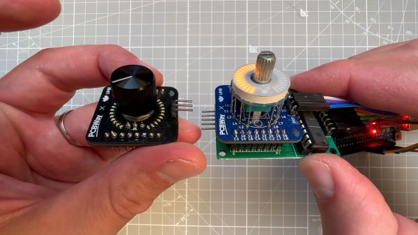
If there’s one thing we like around here more than seeing an improved version of a project we’ve already covered, it’s when the improvements make the original project cheaper. In the case of this LED ring light for pots and encoders, not only is it cheaper than its predecessors, it’s better looking and easier to integrate into your projects.

Right from its start, [upir]’s “Pimp My Pot” project has been all about bringing some zazzle to rotary controls. Knobs with a pointer and a scale on the panel are okay — especially when they go to eleven — but more lights mean more fun. The fun comes at a price, though; the previous version of “PMP” used an off-the-shelf LED ring light with a unit cost of about $10. Not the end of the world, perhaps, but prohibitive, and besides, where’s the fun in just buying a component specifically made for rotary control indication?

The new version shown in the video below is pin-compatible with the driver board [upir] used for the previous version, which is based on the MAX7219 display driver. Modifying the previous board to accommodate 32 white 0402 LEDs over a 270° arc was no mean feat. [upir] covers both creating the schematic and the PCB layout in some detail, providing his usual trove of tool-chain tips for minimizing the amount of manual work needed.

Wisely, [upir] chose to get his boards assembled by the vendor; getting all those LEDs to line up perfectly is a job best left to the robots. While the board is designed for use with pots that mount on either side, we much prefer mounting the pot’s shaft through the board, as it keeps the LEDs closer to the knob. The final price per board works out to about $6.30 in quantities of ten and falls to a trivial $1.70 each for lots of 1,000. Pretty sweet savings on a pretty sweet-looking build.

This is a cool use of a ring of LEDs, but if you prefer the finger kind, you can make that, too. You can do it the easy way or the hard way.

Continue reading “Pimp My Pot Redux, Now Cheaper And Even Better”

Roll Your Own Servo

Usually, when you want a servo motor, you simply buy one already made. But if you need something unusual, you can turn any DC motor into a custom servo you can control just like [Dejan] did. You can watch a video of the process below.

The custom servo can tune the endpoints, the center point, and the sensitivity. It also can be set to handle continuous rotation. A 12-bit encoder tells the microcontroller where the motor is and the output drivers can handle over 3 A of motor current. The microprocessor is a tried-and-true ATmega328. [Dejan] wanted to make the board as small as possible, and we think 40 mm square isn’t bad at all. There is also a 3D printed gearbox and housing. Overall, a very well-done project.

The motor control uses a PID algorithm. Potentiometers set the end range and sensitivity. A push button allows resetting the center position. DIP switches control the mode. The video shows a computer and an RC controller setting the position of the motors.

We have, of course, seen many variations on this idea. We’ve also seen servos rebuilt for better performance.

Continue reading “Roll Your Own Servo”

Kino Wheels Gives You A Hand Learning Camera Operation

Have you ever watched a movie or a video and really noticed the quality of the camera work? If you have, chances are the camera operator wasn’t very skilled, since the whole point of the job is to not be noticed. And getting to that point requires a lot of practice, especially since the handwheel controls for professional cameras can be a little tricky to master.

Getting the hang of camera controls is the idea behind [Cadrage]’s Kino Wheels open-source handwheels. The business end of Kino Wheels is a pair of DIN 950 140mm spoked handwheels — because of course there’s a DIN standard for handwheels. The handwheels are supported by sturdy pillow block bearings and attached to 600 pulse/rev rotary encoders, which are read by an Arduino Mega 2560. The handwheels are mounted orthogonal to each other in a suitable enclosure; the Pelican-style case shown in the build instructions seems like a perfect choice, but it really could be just about anything.

To use Kino Wheels, [Cadrage] offers a free camera simulator for Windows. Connected over USB, the wheels control the pan and tilt axes of a simulated camera in an animated scene. The operator-in-training uses the wheels to keep the scene composed properly while following the action. A little bit of the simulation is shown in the brief video below, along with some of the build details.

While getting camera practice is the point of the project, that’s not to say Kino Wheels couldn’t be retasked. With a little work, these could be used to actually control at least a couple of axes of a motion control rig, or maybe even to play Quake.

Continue reading “Kino Wheels Gives You A Hand Learning Camera Operation”

Not A Pot, Not An Encoder: Exploring Synchros For Rotational Sensing

We’re all familiar with getting feedback from a rotating shaft, for which we usually employ a potentiometer or encoder. But there’s another device that, while less well-known, has some advantages that just might make it worth figuring out how to include it in hobbyist projects: the synchro.

If you’ve never heard of a synchro, don’t feel bad; as [Glen Akins] explains, it’s an expensive bit of kit most commonly found in avionics gear. It’s in effect a set of coaxial transformers with a three-phase stator coil and a single-phase rotor. When excited by an AC reference voltage, the voltage induced on the rotor coil is proportional to the cosine of the angle between the rotor and stator. It seems simple enough, but the reality is that synchros present some interfacing challenges.

[Glen] chose a surplus altitude alert indicator for his experiments, a formidable-looking piece of avionics. Also formidable was the bench full of electronics needed to drive and decode the synchro inside it — a 26-volt 400-Hz AC reference voltage generator, an industrial data acquisition module to digitize the synchro output, and an ESP32 dev board with a little OLED display to show the results. And those are impressive; as seen in the video below, the whole setup is capable of detecting tenth-of-a-degree differences in rotation.

The blog post has a wealth of detail on using synchros, as does this Retrotechtacular piece from our own [Al Williams]. Are they practical for general hobbyist use? Probably not, but it’s still cool to see them put to use.

Continue reading “Not A Pot, Not An Encoder: Exploring Synchros For Rotational Sensing”

Make Your Own Pot And Encoder Knobs, Without Reinventing Them

Rotary potentiometers, switches, and encoders all share a basic design: adjustment is done via a shaft onto which a knob is attached, and knobs are sold separately. That doesn’t mean one knob fits all; there are actually a few different standards. But just because knobs are inexpensive and easily obtained doesn’t mean it’s not worth making your own.

A simple and effective indicator can be easily printed in a contrasting color.

Why bother 3D printing your own knobs instead of buying them? For one thing, making them means one can rest assured that every knob matches aesthetically. The ability to add custom or nonstandard markings are another bonus. Finally, there’s no need to re-invent the wheel, because [Tommy]’s guide to making your own knobs has it all figured out, with the OpenSCAD script to match.

By default, [Tommy]’s script will generate a knob with three shims (for interfacing to a splined shaft) when pot_knob(); is called. The number of shims can be adjusted by modifying potKnobDefaultShimCount. To give the knob a flat side (to interface with D-shafts), change flatted = false to flatted = true. And for adding a screw insert suitable for a set screw? Change tightenerDiameter = 0 from zero to the diameter desired.

The script is quite comprehensive and has sensible defaults, but it does require a bit of knowledge about OpenSCAD itself to use effectively. We have covered the basics of OpenSCAD in the past, and if you’re ready for a resource that will help you truly master it, here’s where to look.