[Oscar] wonders why hobby projects ignore all the powerful brushless motors available for far less than the equivalent stepper motors, especially with advanced techniques available to overcome their deficiencies. He decided it must be because there is simply not a good, cheap, open source motor controller out there to drive them precisely. So, he made one.
Stepper motors are good for what they do, open-loop positioning along a grid, but as far as industrial motors go they’re really not the best technology available. Steppers win on the cost curve for being uncomplicated to manufacture and easy to control, but when it comes to higher-end automation it’s servo control all the way. The motors are more powerful and the closed-loop control can be more precise, but they require more control logic. [Oscar]’s board is designed to fill in this gap and take full advantage of this motor control technology.
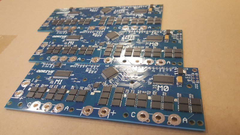
The board can do some pretty impressive things for something with a price goal under $50 US dollars. It supports two motors at 24 volts with up to 150 amps peak current. It can take an encoder input for full closed loop control. It supports battery regeneration for braking. You can even augment a more modest power supply to allow for the occasional 1 KW peak movement with the addition of a lithium battery. You can see the board showing off some of its features in the video after the break.


holy crap thats fast!
It looks like the lead screws have a very fast pitch on them so the motors are not turning quite as fast as you think. It a tradeoff of resolution for speed.
Watch in HD, it’s cable driven, no leadscrews.
Oh, I see it now. What I thought were screws were the shafts and what I thought were nuts are linear bearings.
I dont see lead screws, I see wire drives
It reminded me of this for some strange reason,
https://youtu.be/qgNsTOc_MIo?t=24
yea I see the connection. cool.
Great job. I can see this as a 3d printer. The filament going all over the place.
Nice, I use servos for almost all of my motion control projects. You can get used motors and drives off ebay for pretty reasonable prices but you really have to know what you are looking at a lot of the newer motors and drives can not be mixed and matched with their serial encoders.
I will be curious how he will handle tuning, that is the biggest issue of the non-commercial drives, it takes forever.
The plan is to have fully automated commissioning, with automatic tuning.
Looks quite fast. But more interesting would be the precision and the precision under load, since fast is easy with a brush less motor and not the point of this project. I’m exited to see benchmarks for the precision, if the precision is high and no overshots occur that could be a true game changer I think
That’s just a matter of calibration. The project is already a game changer, no question here. It is providing everyone with a really nice PCB design that proves to be capable of driving brushless motors in a closed-loop fashion. Kudos to Oscar and Josh for open-sourcing the project.
I would say closed loop is definitely the way to go, since than you get rid of the loosing steps problem. And I have to say it is not the first project for a servo motor driver, but steppers are still used everywhere in the DIY community. I suspect the reason might be that calibration and PID tuning is difficult when you want precision. With a stepper you have a lot of drawbacks, but what it can do it does mostly out of the box.
All Kudos to Oskar, Tom and I have put the initial 3 boards together (So I suppose we can take a little kudos), but the design and work behind it is Oskar’s. But I must agree, I think this project will change the way people approach the upper end of hobbyist robotics. The most unfortunate thing about the project is that now all robots need to be mechanically strong enough to take multiple kW on each axis! I know that most of us would not be able to avoid turning things ‘all the way up’ ;)
Well, if you look at the star the machine has drawn, you will see that the accuracy in the demo isn’t great – there are a lot of glitches. It is certainly at least partially due to the construction of the machine as well, but there are also overshoots visible. At that speed also the rigidity of the machine starts to be a limiting factor because even with a lightweight carriage there are significant kinetic energies at play.
I have built a servo drive using an old inkjet mechanics – a DC motor and a optical linear strip encoder – before and those can be quite accurate if you tune the PID well. I was able to obtain the position of the printer head carriage within an encoder “tick” or two of the setpoint, repeatedly. With a cheap 600dpi strip that’s about 0.08mm – 0.1mm resolution. With a better encoder it could be improved, but the strips are not easy to get – almost all cheap inkjets using these are 600dpi only (or 1200dpi software interpolated).
Just have to find the source that the inkjet manufacturers are using. Everything are outsourced, so would be very surprised that there isn’t a specialized printing shop that can mass produce these. Getting the cash flow for volume is something that a crowd funding can help.
For small volume, you can print to film using imagesetter in full-service print shops. https://en.wikipedia.org/wiki/Imagesetter
I wonder if you could send an image to walgreens to have it digitally output to a 35mm slide?
Yay Inkscape and its extensions:
– http://www.dgkelectronics.com/inkscape-optical-rotary-encoder-disc-generator-added-gray-encoder-support/
Just grab a black and white film for analog camera, a strobe light some black paper and a lens or two. Place a strobe light first, then a frame with black paper in which you cut a slot, then a set of lenses to make that slot as small as possible, then just move film across the small line of light with constant speed, while strobe is working. this way you can get a film with exposed stripes of varying length depending on speed of film and strobes per second setting. Then just develop the film and Bob’s your uncle…
How about using a magnetic tape and a head from cassette player? Record square waves on the tape, then use it the same way you use those linear encoders from printers. Make head move over that tape without actually touching it, and take the signal from it to high-gain amplifier, and then to controller. You can even use multiple frequencies while recording to get additional markers on the tape. If frequency A will be ten times higher than frequency B, and that one will be ten times higher than frequency C, and signal C will be high only for 5mm of tape, then you get marks every 10mm, 1mm and 0,1mm…
First you need to construct a lightproof place to do this, then also consider that when wrapping it around a drum the outside radius changes as it wraps over itself(and therefore speed and spacing), so don’t do that.
use the principle of vernier callipers, with a 600 dpi strip casting the shadow as the fixed scale and a linear CCD strip as the moving (vernier) part?
Their demo goes over each line twice in opposite directions… It’s so precise it’s dead on each time. And this demo is only at a fraction of full power.
I would love to see a slow turning motor with this setup. Oh and where are the files? Hopefully it is a kicad design. :-)
Then you should look at my CNC machine that uses servos instead of steppers. The motors are brushed, but the point I’m making is closed loop control as a better alternative to steppers.
https://www.youtube.com/watch?v=j56nl06Ok0U
I really don’t think steppers are much easier to drive, if at all. (And weight? When was the last time you saw an R/C airplane powered by a stepper?) What you trade for the encoder part is constant current power supplies (a separate one for each axis, ideally!), micro-stepping and all its torque woes, and still, at least 4 drive transistors per motor. A 3-phase brushless only needs a 6-transistor H-bridge, whereas a bipolar stepper takes two H-bridges (8 transistors), to make an apples-to-oranges comparison. Blah. Give me clearpath servos if I can’t build my own servos. I consider steppers a very crude device, a sort of rotary solenoid.
the number of transistors is a somewhat moot point when you can get numerous single chip stepper drivers
I am not talking about steppers, I am talking about three phase motors (called brushless)
He wonders why 3D printer makers prefer stepper motors? Well, look at the board he made! Awesome work, but two motors only and already a lot more complex than a printer controller for 4 steppers and 2 heaters. That’s why.
Steppers simply work too well for building up a strong demand for a replacement. And they’re brushless, too, actually kind of a 2-phase BLDC. They trade a pretty complex feedback mechanism for some 50% overpowering and the choice in this trade is pretty clear for rather low torque applications.
That said, servos do make sense where low weight and high power are crucial. E.g. on an extruder head.
To be fair, his board is for 150A, whereas most stepper motors have only 2 amp controllers…
For this application the fairly new STM32F334 seems like a better choice due to its high resolution timer (217ps!). Sure, the STM32F405 has USB and a boatload of flash and SRAM, but I don’t see the need here…
This seems to be a good fit for many smaller high-revolution machines.
Of course, the comparison with industrial servo drives is a bit “optimistic” to express this politely. E.g. the power rating for industrial drives is usually such that you can safely use an 800% overload factor for positioning torque/current. That means, even a small size 400W servo drive needs a multi-kilowatt inverter/power supply that can easily trip a US 15A/115V circuit breaker. Even for a single-axis drive. And of course, those are available in any size you need – the comparison diagram seems to suggest there were no industrial drives available above 1000 Watts continuous power…
Admittedly, the limiting factor for industrial servo drives above a few hundred watts power is usually not the electronics but the tens of tons of reinforced concrete foundation/base necessary to withstand the reactive forces of the rapidly reversing moving masses..
But then again, if you want to experiment yourself or can not afford a big investment, this is maybe a better solution than a stepper motor for a table-sized CNC machine, at least for the reduced noise and vibration and for the closed-loop control.
Wow, Kudos and thanks for this project. Can’t wait to get my hands on the board.
With it open source, I expect it’ll become like Arduinos and RAMPS etc. Available from China dirt cheap at some point.
Would this work with a brushed motor?
Is the controller compatible with stepper motor type (step/direction) control signals. I.e. can you drive it from existing controllers like GRBL?
Hey everyone,
There is now an update about board availability and the roadmap for the ODrive features on the project page (https://hackaday.io/project/11583-odrive-high-performance-motor-control/log/40702-boards-and-development).
If you are interested in getting an ODrive board, you should check it out.
Cheers!