Quick: What’s the forward voltage drop on a conducting diode? If you answered something like 0.6 to 0.7 V, you get a passing grade, but you’re going to have to read on. If you answered 
T0 and k are device-specific constants to be determined experimentally, you get a gold Jolly Wrencher.
 [Jakub] earned his Wrencher, and then some. Because not only did he use the above equation to make a temperature sensor, he did so with a diode that you might have even forgotten that you have on hand — the one inside the silicon of a MOSFET — the intrinsic body diode.
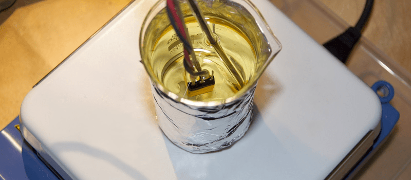
[Jakub]’s main project is an Arduino-controlled electronic load that he calls the MightWatt, and a beefy power MOSFET is used as the variable resistance element. When it’s pulling 20 or 30 A, it gets hot. How hot exactly is hard to measure without a temperature sensor, and the best possible temperature sensor would be one that was built into the MOSFET’s die itself.
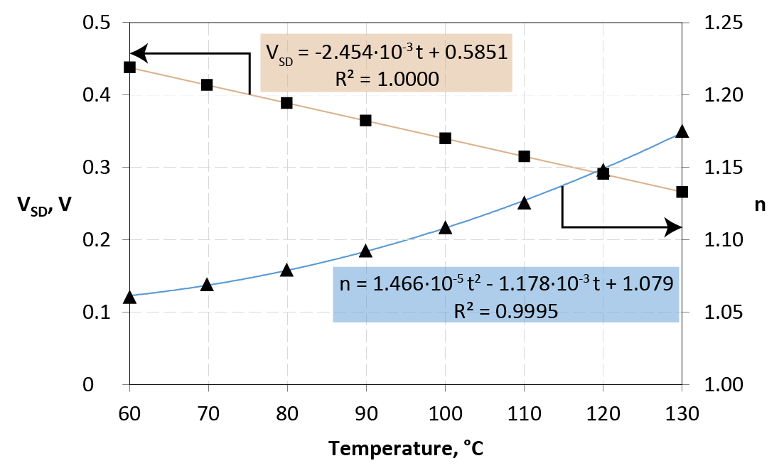
There’s a bunch of detail in his write-up about how he switches the load in and out to measure the forward drop, and how he calibrates the whole thing. It’s technical, but give it a read, it’s good stuff. This is a great trick to have up your sleeve.
And if you’re in the mood for more stupid diode tricks, we recommend using them as solar cells or just stringing a bunch of them together to make a thermal camera.


That’s a clever technique. The die temperature reading isn’t going to get accurate than that. I’m surprised he hasn’t patented it (or has somebody else already have?)
The drawback is that you have to turn the transistor off and reverse bias the diode, which is not something possible everywhere. If you look at the parts required to do that on the schematic, you will hardly call this a ZERO PARTS-COUNT.
If he wanted to be smart about this, since he only needs temperature protection, he could have used one of the smart NMOS switches that contains temperature protection inside.
also, some manufacturers do have MOS transistors with separate diode included http://www.nxp.com/documents/data_sheet/BUK9107-40ATC.pdf
Jakub is using this to calibrate an external thermistor. He isn’t using this as the actual thermal protection for the MightyWatt.
yeah, you are right.
It’s a great hack but as mentioned it would be difficult to implement in practice. One to be aware of but not for every design.
Glad to see stuff like this.
This is how semiconductor manufacturers determine thermal performance.
http://www.engr.colostate.edu/ECE562/lecture_supplements/l6_supp1.pdf
Freewheeling current can make implementation easier.
https://hal.archives-ouvertes.fr/hal-00413325/document
Most application notes like to point out it could be used on body diodes, but few detail how to do it simply.
http://www.thermengr.com/An_Introduction_to_Diode_Thermal_Measurements6.pdf
If you’re going to take empirical test data anyway, and your circuit is an electronic load, which means you are already measuring vout for regulation and vin for under / overvoltage lockout, and you are using a silicon MOSFET whose Rdson rises linearly with temperature, why not just measure the voltage drop across the rdson?
If it’s an electronic load you already are measuring the current anyway.
Wouldn’t work since it isn’t used as a switch. The rdson is controlled by the gate voltage.
What could be done is using the voltage and current to calculate power and then model the temperature
of the transistor with that as input
but then you need to know the environment temperature and the thermal resistance to the environment heat bath, the heat capacities along the way… this method is much more direct
sure but once calibrated it can be a safe and very fast protection mechanism, it beats any external thermal sensor because it can take into account the short time constant of the die. The environment temperature you can probably estimate it’s usually going to be in a limited range anyway
I answered with the Ebers-Moll equation. Can I get an adult sized Snickers – if they still make them?
This wins you two fun sized marathon bars back to back with the best before dates crossed out.
“If you answered something like 0.6 to 0.7 V, you get a passing grade”
Booo… no, you fail. I would at least want to hear .6 to .7 for Si, .2 to .3 for Ge. I would also give extra credit for ~1V / stack Selenium although I wouldn’t expect to be giving out that extra credit very often!
Nice, but why is everyone forgetting that the forward drop on a diode depends on the current too?
I can’t be the only person that’s gone through schottky diode datasheets and given up trying to rectify 10’s of amps with them. Dammit, I want my other half a volt back.
… and that said forward current across forward voltage will cause some amount of self heating …
Actually, I’d put that as a fail too. As above, it is highly dependent on current (V is proportional to log(I), until resistance starts to dominate). It depends on the particular diode as well – plenty of silicon rectifier diodes have rated forward voltages of 1 V or even higher. And of course, if you really want different types mentioned, I would expect Schottky diodes (with a drop of somewhere around 0.3 V to 1.5 V) to be mentioned long before Germanium or Selenium diodes…
… and Vf is even lower for Gallium Arsenide Diodes (GaAs)
oops … and Vf is even higher for Gallium Arsenide Diodes (GaAs) – around 1.2v
I am just waking up. The above made my eyes gloss over, and, I probably wouldn’t understand even if I was awake. However, it seems that something similar to this was done in my 100-in-1 electronic experimenters kit. Instead of a MOSFET they used a TO-92 transistor. I don’t remember the circuit at all. It was hooked up to the included analog gauge and was described as a thermometer.
It was likely a 2N3904.
Something like this?
http://www.sensorsmag.com/sensors/temperature/temperature-sensor-tips-and-tricks-1439
Or something like this:
http://www.buchanan1.net/temperature_logger.html
The design is not truly rigorous, but it did its job well. Also, the refrigerator never failed again…
I often use a 1N914 or 1N4148 for temp measurement with micro-controllers as there small size means they have a low thermal mass and respond to temp changes faster.
They’re not terrific but they have a reasonably linear slope around commonly measured room temperatures.
For a wider range you can use a look up table or “do the math” with only one measured variable (Beta).
For more accuracy you can use an op-amp as well, especially ones that have an internal voltage reference like a LM10. That way you can match the range of voltages to the range of the analog input. Even in the Arduino environment you can select an external analog reference by setting registers.
Just yesterday I saw a place in a PC BIOS where you can enter a Beta for temp measurement – obviously they’re just using a diode as a sensor.
So a diode is the obvious and economical choice where accuracy is not critical. A DS18B20 is a couple of bucks and a couple of bucks will buy you a hundred or more 1N914 / 1N4148’s.
Also old audio amps use a transistor in much the same way. Without some compensation the junction bias in the output stage increases with temperature – which increases the junction bias – which we all know is the formula for magic smoke.
quite a few big IC like FPGAs and CPU bring out two pins connected to an on-die diode (diode connected transistor) for a temperature monitor