Young electronics hackers today are very fortunate to grow up in an era with both a plethora of capable devices to stimulate their imagination, and cheap and ready access to them. Less than the price of a hamburger meal can secure you a Linux computing platform such as the Raspberry Pi Zero, and a huge choice of sensors and peripherals are only an overnight postage envelope away.
Casing back a few decades to the 1980s, things were a little different for electronically inclined youth. We had the first generation of 8-bit microcomputers but they were expensive, and unless you had well-heeled parents prepared to buy you a top-end model they could be challenging to interface to. Other electronic parts were far more expensive, and mail order could take weeks to deliver the goods.
For some of us, this was not a problem. We simply cast around for other sources of parts, and one of the most convenient was the scrap CRT TV you’d find in nearly every dumpster in those days before electronic recycling. If you could make it from 1970s-era consumer-grade discrete components, we probably did so having carefully pored over a heap of large PCBs to seek out the right component values. Good training, you certainly end up knowing resistor colour codes by sight that way.
In the Age of Analog Broadcasts
A personal fascination of mine as a young radio amateur was with the analog tuner you’d find in these sets. This was the RF front end that converted the signal from the antenna into a 36MHz intermediate frequency for the set to demodulate and display. These tuners were simple enough devices usually having only a couple of transistors, an RF amplifier and either an oscillator and diode mixer or a combined mixer/oscillator.
Where I grew up in the UK they were all for the UHF TV bands (about 470 to 860 MHz), and they were either mechanically tuned with variable capacitors and cavity resonators or electronically tuned with varicap diodes and stripline resonators on a PCB. They were discrete modules inside the set, usually in a screening can about the size of a pack of playing cards. Their stand-alone nature meant that once removed from the set they offered considerable potential for modification and repurposing to other UHF uses, and an accessible way to learn the ropes of UHF construction.
So this article is in a way a condensed version of something I might have written as a series had Hackaday existed in 1987, or even as a slim paperback volume had I been able to find a publisher gullible enough to accept the experimental electronic musings of an unproven teen. Think of it as an homage to a technology now past that doesn’t quite fit our retrotechtacular series, and if your interests lie in that direction and you have a few old TVs come your way maybe you can draw some inspiration from it.
The basics
![TV tuner front end block diagram. Derived from Chetvorno (Own work) [CC0], via Wikimedia Commons](https://hackaday.com/wp-content/uploads/2016/07/rf-front-end.jpg)
TV tuner front ends followed this model closely whatever decade of the analog era they were made in. Examples from the 1950s and early 1960s would have featured a couple of triode tubes, by the 1970s you would have found bipolar transistors and more recently they would have had MOSFETs or even GaAsFETs. Most recently the local oscillator would have been a frequency synthesiser but in the era we are discussing it would have been a free-running oscillator kept in check by nothing more than a simple automatic frequency control circuit.
Typical devices
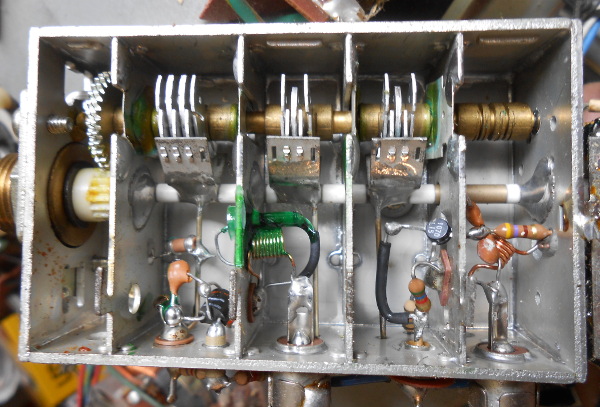
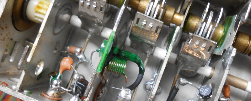
Digging around the half-forgotten electronic junk at the fringes of my workshop I turned up a generic late 1970s 12″ portable with a typical Japanese UHF tuner of the period. A bit of screwdriver work had the cover off, and you can see the internals to the left.
The tuner takes the form of a series of coupled cavity resonators with a set of linked variable capacitors at the top. On the left at the bottom is the antenna input, and on the right are the gears of the tuning mechanism. The RF amplifier transistor lies on the boundary of the two rightmost cavities while the germanium diode used as a mixer is covered in green lacquer and joins the two cavities on the left. The IF comes out at the bottom of the middle cavity and the leftmost cavity holds the oscillator. Immediately you can see that there is plenty of space in which to modify the circuit, turning it into a UHF hacker’s playground.
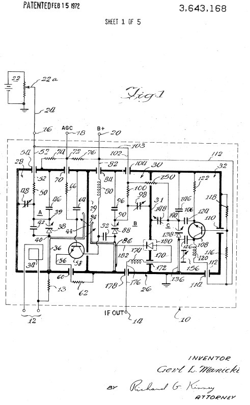
The schematics of this type of tuner didn’t vary too much. We’ve found an example with varicap tuning from US Patent 3643168 which uses a diode mixer like the one above, though you may also see tuners that use the oscillator transistor as a combined mixer.
The most striking thing about this circuit and others like it is their simplicity. The performance of these tuners comes not from clever circuitry but from the highly selective design of their cavity filters. This one differs slightly from the picture above in that it has an input cavity and the mixer shares a cavity with the amplifier output, but other than that and the use of varicap diodes rather than air-spaced capacitors they are extremely similar.
Plenty of RF amplifiers and transmitters
If you were an ’80s teenager with a constant supply of these things there was plenty of scope for experimentation. The simplest hack was to turn one into a super-selective antenna amplifier by removing the mixer diode, applying power only to the RF amplifier, and soldering a UHF-sized coupling loop to the IF connector to turn it into a UHF RF output. Put that in the antenna lead, tune it carefully, and suddenly you’re watching somewhere else’s local news without snow on the picture. You had to take your excitement where you could get it, back in the ’80s.
Of more interest to a young radio amateur was the oscillator cavity. A carefully installed coupling loop could draw a few miliwatts of RF, enough to make a small transmitter. Inject a video signal through a buffer to the oscillator transistor and it made a reasonable video sender covering the whole UHF band, definitely illegal but fortunately not powerful enough to bring the authorities down on a young experimenter.
With some careful soldering it was possible to replace the striplines in each cavity with longer ones folded to fit the space, and to drag all cavities down to operate in the 430MHz (70cm) amateur band. Then it was possible to make either a 70cm ATV receiver or a much more useful transmitter for 70cm ATV by replacing the RF amplifier with a tuned and modulated PA in the same cavities. I hasten to add though, none of my transmitters made this way ever achieved a real-world contact outside the confines of a workshop or radio club meeting.
The only kid in Britain with a spectrum analyser
The piece de resistance of my TV tuner hacking came courtesy of a set that had a completely modular small-signal section. Two screened cans, one of which was a varicap TV tuner and the other of which at about twice the size was a complete IF strip and demodulator. With only a small amount of wiring it could become a complete TV receiver with video and sound output, though that was not the use to which I put it. The tuning voltage of a varicap tuner is 0 to 33 volts, so given a 0 to 33V sawtooth generator and an oscilloscope I had a simple but functioning spectrum analyser.
Sadly the spectrum analyser, built on a piece of tinplate salvaged from a coffee tin, has not survived the decades. I remember it generated its 33V from a 12V supply via a two-transistor multivibrator feeding a diode multiplier, and the sawtooth generator was a particularly nasty thyristor relaxation oscillator. With a bit of tweaking of the IF strip to narrow the bandwidth though it gave a good picture of the UHF TV band on the ‘scope, through which you could see all four of the local TV channels and smaller spectra of those from further afield. With the honesty of hindsight, other than allowing me to say I had a spectrum analyser among my test kit it was pretty useless, but hey! I was the only kid in Britain who could say they’d built a spectrum analyser.
It was quite a job to find a tuner for the photograph above, they have so disappeared from the background noise of electronic junk these days. The portable TV I found had my modification from back in the day as a video monitor, probably the reason why I hung onto it. They may be a technology long past, however I still retain a soft spot for these tuners because it was through them I learned my way around the intricacies of UHF construction. I often hear it said that RF design is some kind of black art, to which I would reply that if that is the case then it is one you can only pick up by experience. Perhaps I was lucky to be given the means to gain that experience in every dumpster.


You can also find the varicap tuners in old cable boxes. The IF in these is fairly broadband (6 MHz analog TV channel bandwidth), but the will work as spectrum analyzers, after a fashion. I once powered one up, hooked the ramp output from a signal generator to the tuning input and synced it with the X axis of my scope. Sure enough, I got a spectrum of the cable channels on the scope!
Probably obsolete, now, what with the DVB dongles and SDR software that’s out there.
Jenny List – I wouldn’t be so fast to cannibalize an old analog UHF TV. Here in USA our old UHF sets can receive 470-890 Mhz. Do the maths. Can you imagine what analog services still in operation can be listened too in this band? Of course it would be slope-tuning of narrow-band UHF FM. And some traffic is digital and there is no squelch. Some of these frequencies are deliberately absent on our police scanners thanks to short-sighted US Congressional oversight.
And according to some retro TORNADO chasers… you can use the VHF low-band tuner to monitor the approach of some vortexes and thunderstorms. Evidently there is a huge EMF component in a mesocyclone and twisters. Odd effects can be witnessed from a safe distance. This TV trick is allegedly debunked by the usual mainstream academia suspects but I think the jury is still out. You can even monitor approaching electrical storms by adjusting CRT brightness to threshold. The closer the frequency is to near 6m band (55 Mhz) the better. All is alleged and needs more empirical experimentation.
Popular Mechanics March 1969 – https://goo.gl/AqSBzs
You’re far better off using a dongle and SDR software for that 470-890 band. But the cellular stuff has been digital for several years, so probably not a lot to hear there.
Monitoring approaching storms is as easy as going to https://www.lightningmaps.org/#m=sat;r=0;t=3;s=0;o=0;b=;n=0;y=42.4231;x=-71;z=5; and they tell you how to build a detector and join their network, too.
Antron Argaiv – Of course that would be the way to go NOW. But us RETRO guys still like dabbling with old school stuff. Imagine knowing when a TWISTER is nearby with an old retro TV set. Of course I could just listen to the NWS but where’s the fun in that? Back in the 1960’s our NWS wasn’t that good at tornado warnings. Didn’t get good at weather Doppler radar until early to mid 1970’s
Great article, Jenny!
Here in the UK there is very little analogue stuff left up there, it’s all digital. And agreed about fun with VHF tuners, it’s just that our sets didn’t have them fitted.
I agree with the poster making the comment about RTL-SDRs. When they cost so little they make the most sense as quick hack/experiment receivers at VHF/UHF.
“but hey! I was the only kid in Britain who could say they’d built a spectrum analyser.”
I doubt that, while I did not live in Britian I knew many hams who had performed similar experiments (not in the UHF, but in the ham bands of course). Doesn’t exactly take a genius to connect a tunable filter to a power detector and ‘scope.
Sorry to disagree but a for “kid” I kind of think it does.
Really? How many of those hams that made their own analyzers were teens?
I’m curious whether you are just trying to be rude, or happen to live in an area with an unusually high average IQ.
Well, I have few hb analyzers. The present kid skill is to find an application (no work), and rubb the lcd display (no thinking). Definitely, there is a lower IQ resulting from over-fostered kids. Do you write? what do you read? what do you learn and build?
To be honest, I doubt it too. Poetic licence, and all that.
I see no reason to doubt Jenny. The spectrum analyzer build was well covered in the electronics hobbyist press. Not so complicated to be beyond the capabilities of a younger hobbyist. Ironically you seem to lack the knowledge to be able to pull off that build, as you over simplified what it takes to construct it. Good Grief…
Great article, Jenny. Well done as usual.
Also, kudos on building the spectrum analyzer when you were young! That is simply awesome!
Thank you!
“Then it was possible to make either a 70cm ATV receiver…”
That’s what I was trying to remember! You can view ATV on an old TV set that was cable ready. Tune to cable 57 to 60 with an external aerial (obviously not plugged into your cable TV receptacle) – and you can capture some live ATV broadcasts in your area… http://www.hamtv.com/
Sadly our TVs never came with cable tuners :(
You could view ATV on many of those old TV sets (UHF channel 21 is at 471 MHz and many tuners could tune lower, and others which could not, could be modified for the purpose), way before cable tuners came along…
Back in the first half of the eighties, in Serbia (ex Yugoslavia), I was a member of a local radio-amateur club where we set up an ATV transmitter and emitted service information for our town. We even had a TV set in centre of the town where passers-by could view our program which we aired around the clock. We used ZX Spectrum to generate graphics with a program named Dlan, whose machine code I had to modify to serve our purpose. Also, I made a cyrillic instead of latin font for Dlan.
In those days in Yugoslavia, only 2 TV channels existed, and things leading one to another, soon we were getting invitations from towns accross the country (now Croatia, Bosnia and Herzegovina…) to come, set up a temporary TV station and emit local TV program. In the evenings, it was nice to see when, after our asking for viewers to start turning their lights on and off if they are watching us, the whole towns would flicker :)
I know this is an old page, but I would definitely read an article about ZX Spectrum powered TV hacking in 1980s Yugoslavia!
Always considered these little things like black-boxes… but that didn’t keep me from saving ’em from nearly every old TV or VCR I’ve scrapped. Surely they could be used for *something*, right? And here it is. Very cool. And a spectrum-analyzer to boot!
I remember playing with cable tv tuners. There was a ‘poor mans spectrum analyser’ set of boards I put together back in the late 90’s. I recently passed that project on to a fellow amateur who was using a rtlsdr dongle that would not quite work well enough for his satellite IF reception. It worked great with an old scope.
Nice to see an article on some old school ingenuity!
Many years ago there was a TV tuner called an “inductuner”. It was a variable frequency VHF TV tuner that used several ganged roller inductors. As I recall it tuned from channel 1, yes channel 1, continuously up to channel 13. At the time I ran the IF output of one into a short wave radio and could tune the frequencies from channel 1 to 13. Of course the SW radio was only AM, but I could listen to the FM stations using slope-decoding.
In about 1977, I did something similar with a UHF TV tuner module. It was before we had 8-bit microcomputers with UHF modulators, but I’d seen an educational circuit in the school’s electronics lab that generated TV sync waveforms and sent them to a TV. It had a discrete-transistor UHF modulator. I took a tuner module and used the local oscillator to make a modulator. I didn’t have a video signal source, but I made a rudimentary TV signal using square-wave oscillators, similar to the way the teaching unit worked. I was able to produce a simple black-and-whit stripe pattern on a TV! Shortly afterwards, TV games and microcomputers came along and make the whole thing obsolete.
where is the cavity resonator in the thing
Those long copper wires in the middle, attached to the ceramic rod, form inductors, which resonate with the shunt variable plate capacitors. The black wires in the 2nd and 3rd compartment loosely couple the resonators to the circuitry.
It’s really not a cavity resonator as the cavity dimensions are much less than 1/4 wavelength. The cavities just shield those lumped resonators.
It’s true, in the past you could get lots of parts from old electronics, now it’s all integrated circuits and tiny SMD components often without clear markings. Less is available to harvest in parts sense, but there are still the connectors and some wiring though.
What’s odd though is that you see tons of projects without cases on HaD and you could source cases from discarded electronics too, or from other throw away items for that matter.
Oh yes.
Even the case for “computer power supplies” can be used. I’ve slapped on piece of copper circuit board (a piece of metal works too) to make a fresh “front panel”, and used the boxes.
But yes, there are endless set top boxes and even DVD players that offer up interesting casing, that is fancier than the average utility box. You’d pay a pretty penny for something that fancy at the parts store.
Older will even have the switching supply as a separate board, just waiting to power your project. More recently, the PS is on the same board as the rest of the electronics, though you might be able to extract it.
One time I needed a “higher” voltage power supply, 18 or 24 volts, and the first inkjet printer I opened (brought home with some vague ide of using one of them as a printer) supplied the needed voltage, on a small board.
Michael
with only power and composite RCA jack and maybe capacitor for input and resistor to charge said capacitor so your composite output does not get fried by your 20-ish volts upon plugging
the secret to transmitting very far (edit: with harmonics of many frequencies) was to attach the transmitting antenna directly to one of the connections in the osc section, a resistor or capacitor might help with impedence matching (capacitor blocks the 20-ish vDC)
… sound not included