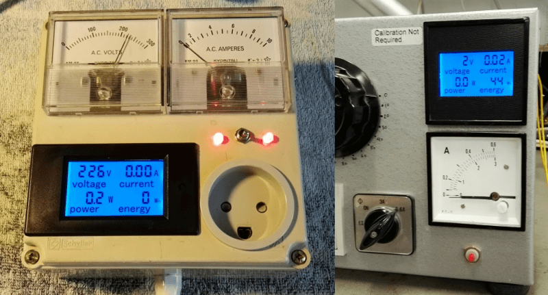
It seems that one can buy cheap power meters online and, well, that’s it. They work just fine, but to use them for anything else (like datalogging or control or…) they need a bit more work. The good news is that [Thomas Scherrer], alias [OZ2CPU], just did that reverse engineering work for us.
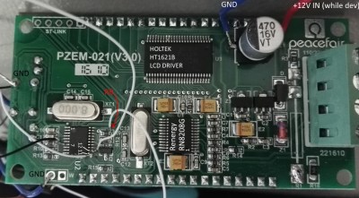
Inside these budget power meters, you’ll find an LCD driver, a power-monitoring chip, and an STM32F030, which is a low-cost ARM Cortex M0 chip that’s fun to play with on its own. [Thomas] traced out the SPI lines that the power-monitoring chip uses to talk to the microcontroller and broke in to snoop on the signals. Once he got an understanding of all the data, tossing an ATmega88 chip on the SPI line lets him exfiltrate it over a convenient asynchronous serial interface.
If you’re going to do this hack yourself, you should note that the internals of the power meter run at line voltage — the 3.3 V that powers the microcontroller floats on top of the 230 V coming out of [Thomas]’s wall plug. He took the necessary precautions with an isolation transformer while testing the device, and didn’t get shocked. That means that to get the serial data out, you’ll need to use optoisolation (or radio!) on the serial lines.
Now that we know how this thing works on the inside, it’s open-season for power-management hacks. Toss a mains socket and an ESP8266 in a box and you’ve got a WiFi-logging power meter that you can use anywhere, all for under $20. Sweet.


Can someone who understands chinese look at the datasheet and tell us if it’s possible to get power factor from the RN8208G?
Or at least raw ADC streams so you can do the calculations yourself…
I think this meter has the same measuring core as the PZEM-004T.
PZEM-004T reports only Voltage, Current, Power and accumulated energy. It is very easy to read from it. I’ve built a circuit using PZEM-004T controlled by a sparkcore in less than 2 hours.
For more info you can google for peacefair pzem-004 or look at the links that I used:
https://github.com/olehs/PZEM004T
https://www.circuitspecialists.com/content/189799/ac004.pdf
Yea, using PZEM-004T is much easier. There are already optoisolation build-in. (but of course too the fun out of reverse engineering!)
I have 2 PZEM-004T tied together, each with a different address, and connected to a single ESP8266-1. Works great!
Oh a side note, I modded my PZEM-004T, replaced the annoying buzzer with a LED, or it will beep for every packet!
Hi dkca,
I’m trying todo the same thing, connecting a PZEM 004T to esp8266 . but not quite working !!
are you using “https://github.com/olehs/PZEM004T” library ?
SoftwareSerial ? What pins are you using on the esp?
Is the VCC on the PZEM 3.3 or 5V ,if 5V are you using a level converter?
I tried my out sample project connecting a PZEM to arduino mega using serial2 , it worked but having a strange behavior , the PZEM hangs for some time after each two consecutive requests. Is this normal?
Hope you can help me
skeezoo
It can be found in datasheet that RN8208G can measure Current effective value, Voltage effective value and active power. So use P=UIcosφ to get power factor.
The problem is how does it get to the “effective value”… if you multiply raw voltage and current measurements that are phase locked, you will get real power, but do anything that disrupts that phase locking and you get bullshit that has little to do with what’s actually going on…
Any kind of averaging that is not the same for all channels (P, U and I) will introduce an error…
+1 Damn right AKA
Its amazing how many “electricians” and even those with a
contractors ticket that get confused on this. Talk about
tri-plen harmonics and you get blank looks – and these people
install power supplies with doubtful power factor correction
then wonder why their neutral/grounds get way too hot – FFS…
If you are interested in PF you are probably better off using an EcoPlug since they have integrated power factor monitoring and wifi already built in. http://hackaday.com/2016/02/06/cheap-wifi-outlets-reflashed-found-to-use-esp8266/
These power meters come in different variants. There is this one, then there is a 100A DC version that has a big external shunt, and 10 and 20A DC versions that have internal shunts. The DC versions of course run off your “DC” supply and not at “line voltage”.
The one I opened up (I don’t remember which one I opened) also had the holtec lcd controller and something interfacing with the power-side. I guess it must be this one (i.e. AC, line voltage) as I remember the power-measuring-chip.
PF is fully handeled by the RN8208G, since you get all 3 tings, voltage, current and power, the “error” is simply the powerfactor, when you manually multiply voltage with current you only get the same watt, with a light bulb
I hope these overcome the primary shortcoming (at least for me) of the kill-a-watt; its inability to deal with modern active PFC computer supplies accurately.
kris, if the kill-a-watt unit use the same metering chip RN8208G ?? then you should expect the same kind of performance, however I do use my many peacefair PZEM-021 meters, for all sorts of mains powered designs, including switchmode supply with passive and active power factors, it does read out the correct usage for me :-) it is only 10 bucks on ebay to try it out.
>Toss a mains socket and an ESP8266
and additional power supply, CR dropper is not enough for ESP8266, trust me iv been there
If you’re somewhere really cold and need to heat the box it’s in… :D
“the 3.3 V that powers the microcontroller floats on top of the 230 V”
Cool! So it even generates extra volts! Or was it just meant to say the 3,3V is line referenced aka float on top of the Neutral / blow the live. Certainly not on top of the 230V…
below, not blow :/
I would like to use this to measure the power of a brew kettle (4400W) controlled by a triac. I am expecting the readings to be a bit off because of the chopped phase.
Would like to run it below 80 volts and thinking this low voltage limitation is simply because the internal powersupply will shut off. It shouldn’t be too hard to split the power supply and voltage sense leads and be able to go lower.
Anyone have a schematic?
T
did somebody try to use the STLINK on this board.?
Is there a way to provide these meters with a supply voltage as well the voltage under test? I’m trying to use a PZEM-061 on a variac to measure the output voltage and current. As the meter comes from the factory I can only measure the source voltage.
Does the Pzem 004t have a power threshold? If so how does that work?
Probably a more expensive units like three phase multi function power meter ( http://s.click.aliexpress.com/e/e6E2BEa ) give more information (power factor, etc, etc ), and have “more isolated” comm ports
Also see https://hackaday.com/2018/05/14/diy-variacs-get-esp8266-upgrades/
Newer revisions use a SOC instead of frontend+STM32 (https://hackaday.com/2018/05/14/diy-variacs-get-esp8266-upgrades/#comment-4597867)