Reflectance transformation imaging (RTI), or polynomial texture mapping, is a very interesting imaging technique that allows you to capture all the detail of an object. It’s used to take finely detailed pictures of scrawlings on cave walls in archeology, capture every detail of a coin for coin collectors, and to measure the very slight changes in a work of art.
RTI does this by shining light over an object at very particular angles and then using image processing to produce the best image. Despite being only a few LEDs and a bit of software, RTI systems are outrageously expensive. For his Hackaday Prize entry, [leszekmp] is building his own RTI system. It’ll cost about $600, making this the best way for Citizen Scientists to capture the best image possible.
RTI is simply shining light onto an object and taking synchronized pictures of the object from directly above. As you can imagine, putting LEDs in a dome is the obvious solution to this problem, and already [leszekmp] has made three systems that works well on domes up to a meter in diameter. The electronics are as simple as an Arduino shield and a few MOSFETS, and the dome itself is an off the shelf component. It’s a great project that enables better photography, and one of the simplest and best entries we’ve seen for The Hackaday Prize.


Very nice project! I’ve seen an alternative technique that involves a diffuse lightsource and a polarizer. The object is photographed with at least 4 polarizer angles. The light reflection angle can then be calculated. My guess is it would be even cheaper since you only need a diffused lightsource. Automating rotating a circular polarizer filter would be a challenge though.
Looks similar to a bump map used in video games.
Cool system and congrats on the results so far! The 600$ price point is a lofty but noble goal so good luck with the project.
Yes, if you mean a normal map then it is very similar to this method,
http://www.zarria.net/nrmphoto/nrmphoto.html
http://www.zarria.net/nrmphoto/crossnrm.jpg
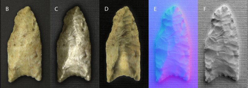
I assume you’re referring to E, which is not a bump map, but a normal map. Bump maps convey only intensity. Normal maps convey both intensity and direction.
Bump maps convey low-relief surface offset, and are used to alter the surface normal across the face of the polygon, just like normal maps. Basically they’re just a cheaper, less flexible version of normal mapping – think of like bump maps : normal maps :: height field : mesh.
Is that not the same technique as in HDR ? Could you take the pictures from the Dome and feed them into a normal HDR Software ?
Definitely not the same technique as HDR (high dynamic range) photography. HDR uses multiple photos of the same scene with the same lighting, at different exposure lengths. This takes multiple photos of the same scene with different lighting, at [presumably] the same exposure length.
Interesting project!
Is this creating bump-maps of real objects for viewing in VR? It seems like that’s what this technique basically accomplishes at a very high resolution.
It’s more for archaeology by the looks of it, some artefacts you find can have incredibly light markings (invisible to the naked eye) on them that are really significant. RTI is an alternative to LIDAR scanning for small objects.
I really want to make a ‘poor-man’s’ version just to see what can be done with my phone, a dozen leds, and the darkness of the night.
This project appears great no matter what angle you look at it. :P
Hmm, a VR archeology simulator game would be both fun and educational. Just seeding the idea…
That would be great!
I would honestly consider supporting a project like that financially. Anything to get newcomers interested in science. :)
It seems like most of the useful part of this project is the software he uses (provided by the CHI), and the actual hardware that this project consists of is not much more than some LEDs mounted to a camera.
The good news is that the construction technique is quite inefficient, and the build cost for the dome can be reduced to sub-$100 fairly easily and theoretically can probably be brought to about $10 in parts for mass production (ie, using flex pcb’s with smd LEDs on them for the illumination and a purpose made dome).
For a quick build I would use the cheap individually addressable LED strips which are available for about $10 for a 60 LED strip (ie, https://www.amazon.com/Led-World-WS2812B-Flexible-Waterproof/dp/B014KO0KA6 ). Combine with an arduino nano clone ($7 https://www.amazon.com/Gikfun-ATmega328-Micro-controller-Arduino-Ek1620x1/dp/B00Q9YBO88 ), 12MP webcam ($14 https://www.amazon.com/Docooler-Megapixel-Camera-Desktop-Computer/dp/B00OB88HI4 ) and the dome suggested by the vendor ($50) you have full rig for a bit under $100 shipped–assuming you already have a computer to run the software on.
I have doubts about that camera, is the CCD really a true 12MP?
I’d recommend something like this, if cameras with such lens systems are appropriate at all.
http://www.dx.com/p/amkov-sj5000s-20-0mp-cmos-1080p-full-hd-wi-fi-outdoor-sports-digital-video-camera-silver-black-384607
I agree with [Dan#8582394734]. The specs for [jrfl]’s last link reads:
“Dynamic resolution: 640 * 480”
No way that webcam puts out comparable video quality for this project, though I think it could be done for far cheaper than $600.
I really like the LED strip idea; do we know how important the diffuse vs. point light source is for this technique?
(Sorry if that question reads weird, not sure how to word that.
A point source is best so the best image is from a very small very bright LED, you could mask them with a pinhole aperture. Diffuse lighting would reduce the difference between images, so what would the point of having them be?
I’ll admit it; that may have been one of the dumbest questions I’ve asked around here.
Probably because I dislike ‘sharp’ light, but that is a key point of this imaging technique. The examples shown look great.
Could you do this with opencv?
Hi,
I would really love to be involved in this project, I do not exactly how this work.
I worked on something to acquired BRDF in the past and I’ve wanted to develop something similar to what you suggest for years.
Some interesting links in my bookmarks :
– http://www.zarria.net/nrmphoto/nrmphoto.html
– http://rtgfx.com/pbr-texture-scanner/
– https://m.facebook.com/story.php?story_fbid=10153800651856843&id=178486766842
Let me know if we could discuss, and why not work together.
Cheers,
stephane-lb
Hi Stephane,
Only saw today that there were comments on the Hackaday blog post about my Reflectance Transformation Imaging system, including yours at the end. A system like the one I’m documenting should be usable for BRDF studies, since it does exactly what’s needed – get intensity data for a point from multiple lighting angles. Working hard now to finish the build and documentation for the 10/5 Hackaday deadline, but if you’d like to contact me after that date with questions/suggestions, I’d be happy to offer any help I can.
HI all,
Project owner here, Leszek Pawlowicz. Sorry for the late response on this – didn’t think to check for comments until now. A few short answers:
– Imqqmi: Not sure about the polarizer technique, but suspect it would only work well with objects where reflected light is significantly polarized.
– Spencer Hamblin: Yup, very similar to bump maps. The output data is in 2D, but the normals calculated for every position make the response to changing light directions similar to that for the 3D object.
– Dan#8582394734: Not exactly the same, but close. The technique fits a 2D curve to the light intensity as a function of angle for every pixel, so that you can simulate the scattered light intensity for any angle. The angle at which the curve intensity is at a maximum is the normal direction, and you can color code that direction similar to the way your normals image is color-coded.
-SlurmMcKenzie: darren is right, this isn’t really HDR.
-notarealemail: You can convert the normal maps into a 3D surface by fitting a surface that fits the direction of the normals at all points. This is similar to the approach used in photometric stereo. But there are issues with getting an accurate surface on a large scale that I won’t go into right now.
-jrfl: TLDR: it’s not that easy. When I first started this project, I thought it could be done for about $100 as well. But there wound up being a host of issues, both technical and practical, that drove up both the price and the complexity. The technique requires that every LED produce as close to the same intensity as possible, which requires current control at some point. I started with 100 mA LEDS (~0.5W), which proved woefully inadequate in intensity for reasonable exposure times even with a full camera aperture (and horrible for small apertures with macro lenses); even 350 mA LEDs (1 W) were too dim for my original 18″ dome, and would be hopeless for the larger domes that I wanted my design to support. The current design uses 1 A / 3W Cree LEDs with current control for high intensity and good light output matching, and it would be a simple matter to modify the design to double the output for even brighter LEDs; these LEDs aren’t cheap from a reputable source (about $3 each if you look around). The light strips you reference use 60 mA of current per LED, less than even my original LEDs, bright enough for their intended display purpose but not bright enough to provide illumination for even a small dome, much less a larger one; no mention of how the maximum current is controlled, either. Larger matters because the rule of thumb for RTI is that the largest object you can accurately image is 1/2 the distance from the light source to the object, or 3″ for a 12″ dome; I think you can push that a bit and get acceptable results, but you can’t push it too far. There are lots of archaeological artifacts/fossils/manuscripts/whatever that would require a much larger system, and 60 mA LEDs just won’t cut it; my design should work with acceptable speeds for domes up to about a meter in size, and possibly larger depending on your tolerance for long exposure times (1-2 seconds). While the webcam you suggest would be OK for casual use, there’s no way its picture quality or flexibility (speed, aperture control, ISO, white balance) comes close to a decent point-and-shoot or DSLR, and that’s what you want for serious work. And while the vendor quotes about $50 for the dome, what they don’t tell you is that shipping costs will come close to doubling the price – the shipped cost for my dome was $86, not $50. I have several log posts that talk about the design considerations, what I tried in the past and why I rejected it, plus a rough breakdown of the largest cost components. I’ve been working on this for 3+ years now, and have worked through a lot of issues. Believe me, if I could have done it more simply and cheaply, I would have.
-notarealemail: What you really want is an ideal white light source over the area of the sample where all the light rays are uniform in intensity and parallel to each other. There’s really no such thing, the closest practical alternative is a light source very far away, but then you need it to be impractically bright in order to take a picture. That’s why there’s the rule of thumb of “artifact no larger than half the distance from the artifact to the light source”, as beyond that non-parallelness (is that word) of the light rays, along with intensity dropoff due to the inverse-square intensity law and Lambertian LED output dispersion.
-CB4: Can’t do this with opencv, I don’t think.
-stephane-lb: Have just filled out the contact form on your blog.
Thanks for all the comments. If you have any other questions or suggestions, you can contact me directly at l-e-s-z-e-k-m-p-@-g-m-a-i-l.com, or post them here (I’ll be following this a bit more closely.
Leszek
Thank you very much for the repy, and congratulations on winning second place!
Your project was very inspiring to me.