“Ugly” or “Manhattan” style circuit building is popular among ham radio folks. Basically, you solder the circuit point-to-point, using a solid copper plate as a backplane. “Manhattan” gets its name from the little pads and parts of different heights strewn all around the board — it looks like the Manhattan skyline. It’s a great one-off construction method and actually has reasonably good properties for radio/analog circuitry. It’s easy to pull off with leaded components, but gets trick with smaller surface-mount parts.
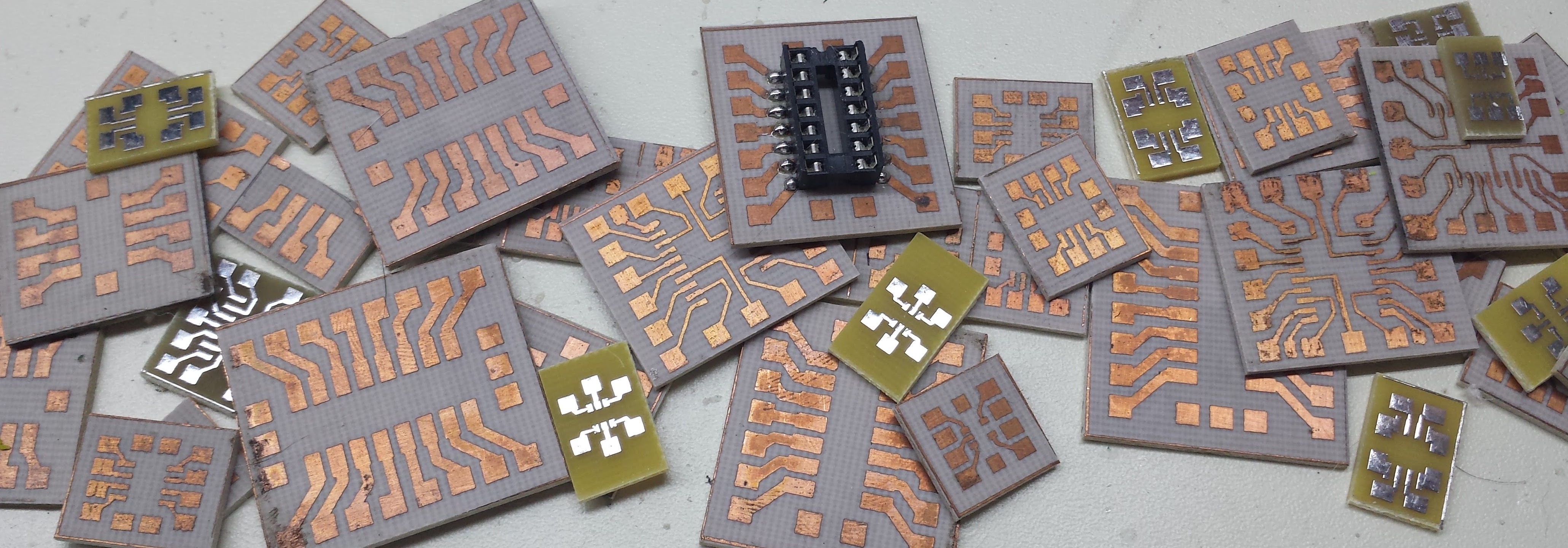
Unless you build some adapters. [Ted Yapo] has made his library of small Manhattan adapters available for us all to use. There’s also no reason to stop with SMT parts — even normal DIP parts can be easily adapted to Manhattan construction, as this teasing photo of a bunch of [Ted]’s adapters shows. And if he doesn’t have the layout you need, the source files should give you a good starting point.
If you want to get started with Manhattan (or other “ugly”) construction, we’ve got a guide for you. And in case you take the “ugly” moniker too seriously, check out this incredibly beautiful ugly build.


Doesn’t get the flux in the way with RF? I suspect it will add lots of capacitive ans resistance coupling
Globs of solder do, so no 2 boards will have same reasonant freq. Really touchy.
If the proper “no clean” flux is used then it would hardly affect the circuit. You should worry more about wire length and routing itself. However, it all doesn’t really matter, this technology is for one-time only circuits, so it’s not a problem if it requires some extra adjustments to make it work. It isn’t any more “touchy” then any other prototype build on a normal PCB, in that case there are also small surprises. And this method allows much more freedom to make a change/patch if required.
So TED great job!
The RF portion of a product im talking about is pretty simple actually. Production part (designed ~20years ago by someone whos gone), wires arent in way of course or the length differences would be very very small…they may be made by hand since its so few components. At higher freqs (10ghz or so) i think solder globs will affect it, and part tolerances. Not my project but ill pass that on, thx.
Not capacitance. Inductance. The stray capacitance is going to be small – the distances to the ground plane (that’s what the copper backplane is for) are large, and capacitance goes as 1/d. Plus it’s running over air, which is a crappy dielectric, so that cuts down the capacitance even more.
But the inductance is determined by the separation between the signal and the return current along the ground plane. Essentially, how high above the plane each of those wires is.
All depends on frequency. HAM builds are mostly in HF range so it does not matter a lot. Even on 145Mhz flux is not a problem.
Adapters are not necessary, You can do mount ICs “dead bug style”, but I recommend to print mirrored pinout, because its very easy to make a mistake.
Pictured construction is really ugly.
Look at this G3XBM construction for example:
http://1.bp.blogspot.com/-l4jxQcXEc8s/RbkmBeIKtLI/AAAAAAAAABg/6S18XEgBbe8/s1600/IMG_0042.JPG
That does not look bad at all. I’ve seen circuitboards that looked much worse.
But it depends. It’s a really good breadboard method, since it’s easy to change things. I had some pieces of circuit board mostly slathered with solder, because I tried endless things, but the circuit board could be reused, no holes.
But that tends to leave a mess, so you either hide it in a box, or redo it on a fresh piece of circuit board.
Michael
And yet, this was probably used at the higher frequencies first. I’ve seen an article, from around 1960, promoting the use of circuit board at VHF. You want short leads, and the traditional aluminum chassis with holes for solder lugs means you may not use the shortest leads. You can solder to copper, so leads to ground can be short, but also the large area of copper is not only small in resistance but small in inductance.
Frank Jones wrote endlessly about receiving converters, and he’d build them on inverted chassis, using a sheet of aluminum over the open side. But then he switched to copper circuit board for the sheet, as transistors became useful higher up. Each new device, Nuvistor, bipolar transistor, FET, he’d have new converters this way, for 50, 144, 220 and 432MHz.
K1CLL, Bill Hoisington, wrote endlessly for “73” magazine, trying to get people o build for the higher bands. And early on he’d use circuit board, easy to solder to, easy to cut and you could make pieces to hold variable capacitors and the like without a metalworking shop.
I started using circuit board fir breadboarding about 1973, maybe someone suggested, but it was before anyone called it “ugly” or “Manhattan style”.
Michael
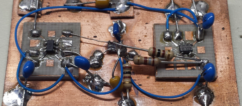
Just for reference (I didn’t mention it in the project write-up), the board in the original image is a prototype for a PCB I later made. It has an XTC7004 16.384MHz TCXO (dead-bug, center), a TC1014 1.8V LDO, and a 74LVC1T45 level translator. I had a prototype done in about half an hour rather than waiting two weeks for the PCBs.
Sorry 16.368 MHz. My brain wants to snap everything to powers-of-two.
Think I like this way of SMD prototyping, will have to give it a go.
If you’re looking for something a little less one-off, several different hobby electronic sites carry breakout boards for SMD components which give you a standard 0.1″ pitch through-hole connection that’s breadboard friendly. I’ve quite liked the ones from Adafruit that I’ve used, but there are a lot of options out there.
Just what I’ve wanted to be able to buy. I hope some enterprising folks in China will offer these on eBay. Great product for using waste space on board runs. No drilling required. Ugly style has become my default prototyping method. It’s much quicker than flea clips on through hole protoboards.
For RF, ugly style is recommended practice because of the need for a good ground plane. Solderless breadboard are a disaster at RF. If you try to use them, you’ll quickly find out why no one else does. Most MCUs clock in the HF region, so it applies there as well. It’s just not as conspicuous as having your oscillator drift or your amp oscillate. Instead you get odd little glitches that send you looking for the bug in the software.
I’m amused by the flux comments. Flux is hygroscopic (absorbs water from the air). I’ve traced quite a few system failures in commercial products to flux residues. Washed off with alcohol and the things worked again. It’s a prime cause for cheap (and not so cheap) consumer electronics failures. The shift to 3 V and below reduces the noise margins to the point where it becomes a serious problem.
Flux is hygroscopic, although some (much) more then others, you certainly do have a point there.
Thanks for mentioning.
I bought some SOIC breakout/prototype board from digikey probably 5+ years, so they exists.
http://www.digikey.com/product-search/en/prototyping-products/adapter-breakout-boards/2360393
I’ve built RF power amplifiers (Down East Microwave) this way, but typically the board had some etching done – the power transistors are typically SMD, but large and only have 4 leads, so hand soldering them is easy. The rest of the components go between designated large planes with edge mount connectors for RF in and out.
Flipping over SMD parts dead-bug does indeed work. Just be careful to use as little heat as possible, as there is no trace or ground plane to absorb heat in this situation. You’ll quickly cook that SMD part if you dwell a bit too long.
Many years ago, I soldered circuits with brass drawing pins on wood. It worked!
Reminds me:
http://imgur.com/a/ViwQH
The DIP-to-Ugly adapters were for a workshop at a hackerspace (and I have some leftovers in a drawer). The SOIC is hand-drawn, and pinned out for a breadboard, but you get the idea.
These are great techniques to lash stuff together in a hurry.
I like this for dip packages a lot better than dead bug style. Gluing the chip on upside down hides the part number, also it means the pin positions are mirrored from what one normally expects.
I’m also feeling kind of inspired, to try this, then should the opportunity present, i.e. a big enough circuit or system that is easily segmented… build a complete monstrosity that uses chassis and terminal strip, actual breadboard and pins, wirewrap, stripboard, one of those gimmicky DIL project boards, dead bug, free form, hand carved PCB, and this all combined…. maybe even have a “module” from one of those educational electronics trainer systems just somehow wired up floating in the middle.
I thought “ugly” was a mish-mash style of direct point-to point trace routing, and “Manhattan” was a style utilizing a more grid-like trace routing(even when it isn’t expressly necessary)