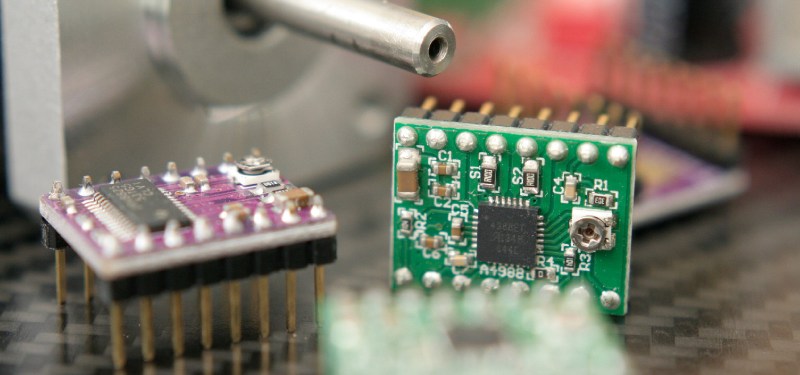
Stepper motors divide a full rotation into hundreds of discrete steps, which makes them ideal to precisely control movements, be it in cars, robots, 3D printers or CNC machines. Most stepper motors you’ll encounter in DIY projects, 3D printers, and small CNC machines are bi-polar, 2-phase hybrid stepper motors, either with 200 or — in the high-res variant — with 400 steps per revolution. This results in a step angle of 1.8 °, respectively 0.9 °.

In a way, steps are the pixels of motion, and oftentimes, the given, physical resolution isn’t enough. Hard-switching a stepper motor’s coils in full-step mode (wave-drive) causes the motor to jump from one step position to the next, resulting in overshoot, torque ripple, and vibrations. Also, we want to increase the resolution of a stepper motor for more accurate positioning. Modern stepper motor drivers feature microstepping, a driving technique that squeezes arbitrary numbers of microsteps into every single full-step of a stepper motor, which noticeably reduces vibrations and (supposedly) increases the stepper motor’s resolution and accuracy.
On the one hand, microsteps are really steps that a stepper motor can physically execute, even under load. On the other hand, they usually don’t add to the stepper motor’s positioning accuracy. Microstepping is bound to cause confusion. This article is dedicated to clearing that up a bit and — since it’s a very driver dependent matter — I’ll also compare the microstepping capabilities of the commonly used A4988, DRV8825 and TB6560AHQ motor drivers.
Microstepping
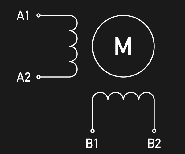
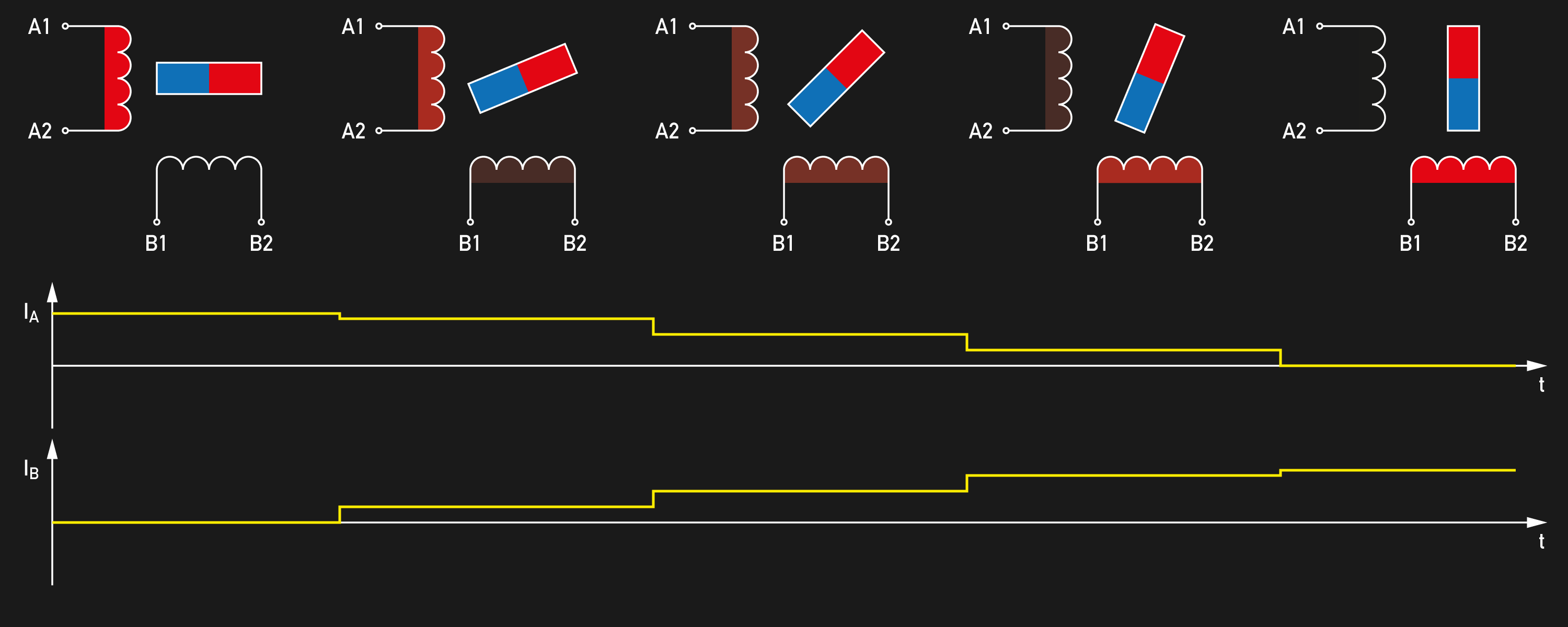
In a hybrid stepper motor, a microstepping-enabled motor driver will adjust the current in the stator coils to position the permanent magnet rotor in an intermediate position between two subsequent full-steps. A full-step is then divided into a number of microsteps, and each microstep is achieved by the two coil currents.
Many older industrial motor drivers feature only 4 microsteps (quarter-step mode), but today, 16, 32 and even 256 microsteps per full-step are commonly found. If we had a 200 steps per revolution stepper motor before, we now have a 51,200 steps per revolution miracle. In theory.
In practice, we’re still dealing with open-loop drivers, meaning that the motor driver does not know the exact angular position of the motor shaft, and it won’t correct deviations. Friction, the motor’s own detent torque and most strikingly, the external load that acts upon the rotor will go unnoticed by the driver. Without closing the loop through an encoder and a more sophisticated special driver, the best we can assume is that the motor will be somewhere ± 2 full-steps (yes, that bad) near its target position, which is the maximum deflection before the rotor snaps into the wrong full-step position, resulting in step-loss.
The incremental torque from one micro step to another is — governed by merciless trigonometry — only a fraction of the dynamic torque of the motor. To ensure that the motor shaft actually sets within +/- 1 microstep, we need to also reduce the load accordingly. Exceeding this smaller, incremental torque won’t result in step loss, but it will cause the same absolute positioning error of up to ± 2 full-steps. The table below shows the devastating relationship.
| Microsteps per full-step | Incremental holding torque per microstep |
|---|---|
| 1 | 100 % |
| 2 | 70.71 % |
| 4 | 38.27 % |
| 8 | 19.51 % |
| 16 | 9.80 % |
| 32 | 4.91 % |
| 64 | 2.45 % |
| 128 | 1.23 % |
| 256 | 0.61 % |
Source: Stepper Motor Technical Note: Microstepping Myths and Realities by Micromo
The good news is, that as long as we use a strong enough motor driver, and if we don’t exceed that incremental torque, be it through an external load or the motor’s internal inertia, the only theoretical limit for achieving microstep positioning accuracy are the motor’s internal friction and detent torque. These values depend heavily on the motor type, but are generally rather low (almost negligible) values. For example, the motor used in the following test is specified with a detent torque of 200 g cm. That’s merely 5% of it’s 4000 g cm holding torque. According to the above table, this motor should be capable of accurate positioning with a 16 microsteps per full-step driver.
So, does this theory apply? And do all microstep motor drivers deliver the same performance in terms of microstep positioning accuracy? I recently had the chance to test a few motor drivers for a project, and I was rather surprised by the results.
Test Setup
For the test setup, I borrowed the red laser pointer from my IR thermometer and attached it to the motor through a 3D printed fixture. A 3D printed mirror mount attaches a first surface mirror to the motor’s shaft and features two levers with a length of 100 mm each for loading the motor with a given mass. For the load test, I attached a mass of 100 g to one lever, which results in a load momentum of 1000 g cm through the lever. That’s a quarter of the holding torque of the motor used for this test: A Wantai 42BYGHW609 with 1.7 A per phase, 4000 g cm holding torque and 200 steps per revolution.


I mounted the motor assembly to a rigid windowsill and positioned it so the laser pointer dot is projected across the room onto a pocket rule attached to the opposite wall, about 6 meters away. The optical lever magnifies the steps for accurate readings. Initially, I planned to just note down the readings manually, but then quickly realized that writing a little Java image processing script to extract the readings from photographs could be done in a fraction of the time. So a DSLR camera was hooked up to my test electronics — an Arduino and a RAMPS 1.4 — to be triggered for acquiring the position readings. I certainly should’ve pointed the laser at the clean, white wall next to the ruler, but a simple threshold on the red-channel did a good job in accurately extracting the bright red laser spot from the ruler. From the reading on the ruler and the distance on the wall, I later calculated the angular position of the motor shaft.


All stepper motor drivers were tested in their 16 microstep per full-step mode. Before the measurement, the stepper motor was brought into a full-step detent position, and the mirror was aligned to a beam perpendicular to the wall. Then 16 microsteps were executed in one direction while triggering the camera after every step. After that, 16 microsteps were executed in the reverse direction, bringing the stepper motor back to its original position. Again, the camera was triggered after each step. Measuring the position in both directions should allow me to get an idea of the motor’s cushioned backlash (if present), but resulted in more interesting insights than expected. This test sequence was executed for every driver, both unloaded and loaded with 1000 g cm. The stronger drivers caused a bit of overshoot during the loaded tests, so they were given time to come to rest before a photograph was triggered.
It’s worth mentioning that all following results originate from the very same motor, and the same physical motor step to ensure comparability. Nothing has been averaged or otherwise processed, except from calculating the shaft position angle. However, all tests have been performed multiple times on different hardware (i.e. the same driver IC, but different breakout boards from different sources) to ensure sanity of the results. Even the quirky results (such as the DRV8825) were reproducible on different setups. Please be aware that the following graphs may give the false impression of a time-continous measurement. They actually show a series of discrete measurements at the marks on the x-axis, and the line graph only should make it easier to see the non-linearities at a glance.
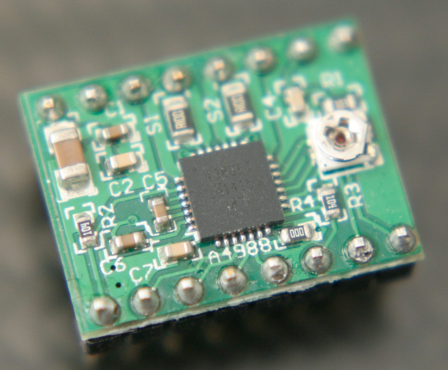
Allegro A4988
The Allegro A4988 on a Pololu-like stepper driver breakout board performed the best, both unloaded and under load. Even though it only delivers 1 A per phase, it achieved very linear, equally spaced microsteps in the unloaded test, with small but reproducible deviations from the ideal position within ± 1 microstep. Interestingly, the A4988 shows its largest deviation at the half-step position.
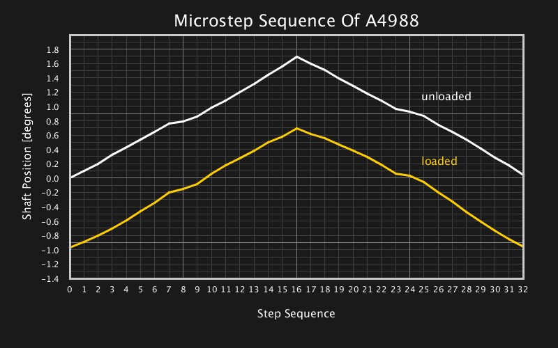
Unsurprisingly, the shaft position is deflected noticeably under load: more than a half full-step. There goes the dream of infinite resolution. However, the graph also shows that the full-step positions aren’t immune to this deflection, even though they are supported by the motor’s slight detent torque.
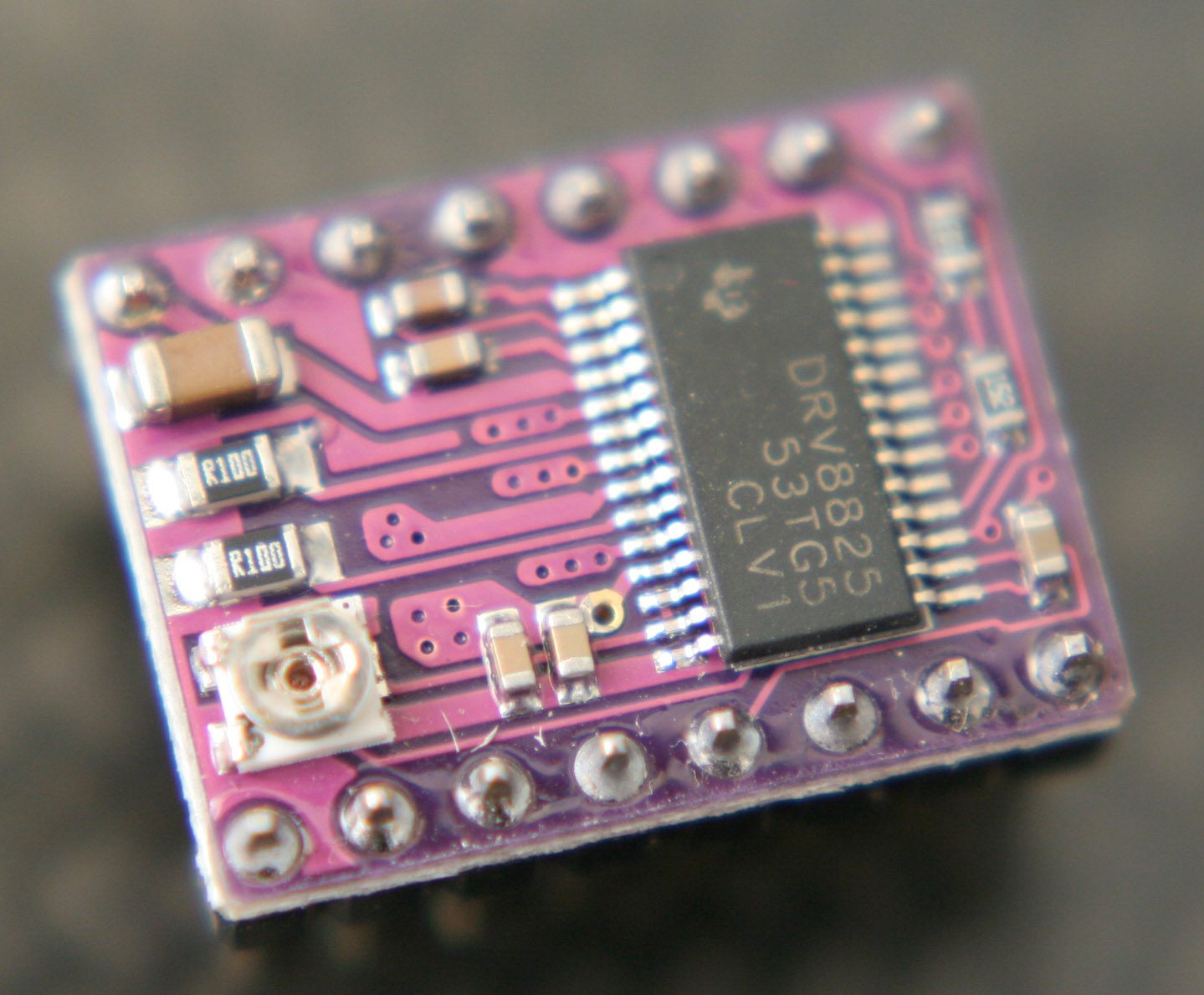
Texas Instruments DRV8825
The Texas Instruments DRV8825 on a Pololu-like stepper driver breakout board performed the worst. I repeated the measurement several times with different breakout boards from different sources, all of them resulted in curves almost identical to this one. However, since the driver is capable of supplying a higher current of 2.2 A to the motor, it shows a significantly smaller deflection under load at the full-step and half-step positions.
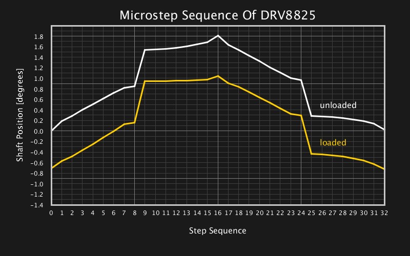
Both loaded and unloaded, the DRV8825 performs well until it reaches the half-step. Then, it leaps almost to the next full-step position within a single microstep. In the reverse direction, it again performs well until it reaches the half-step – this time in the other half of the full-step – before it breaks down to the original full-step position. The behavior is hard to explain. At least deficiencies in the motor’s current sensing path should affect the positioning more uniformly. I’m sure Hackaday readers can contribute to explaining, confirming, or disproving this behavior of the DRV8825, or maybe point out flaws in the measuring setup that could’ve caused these results.
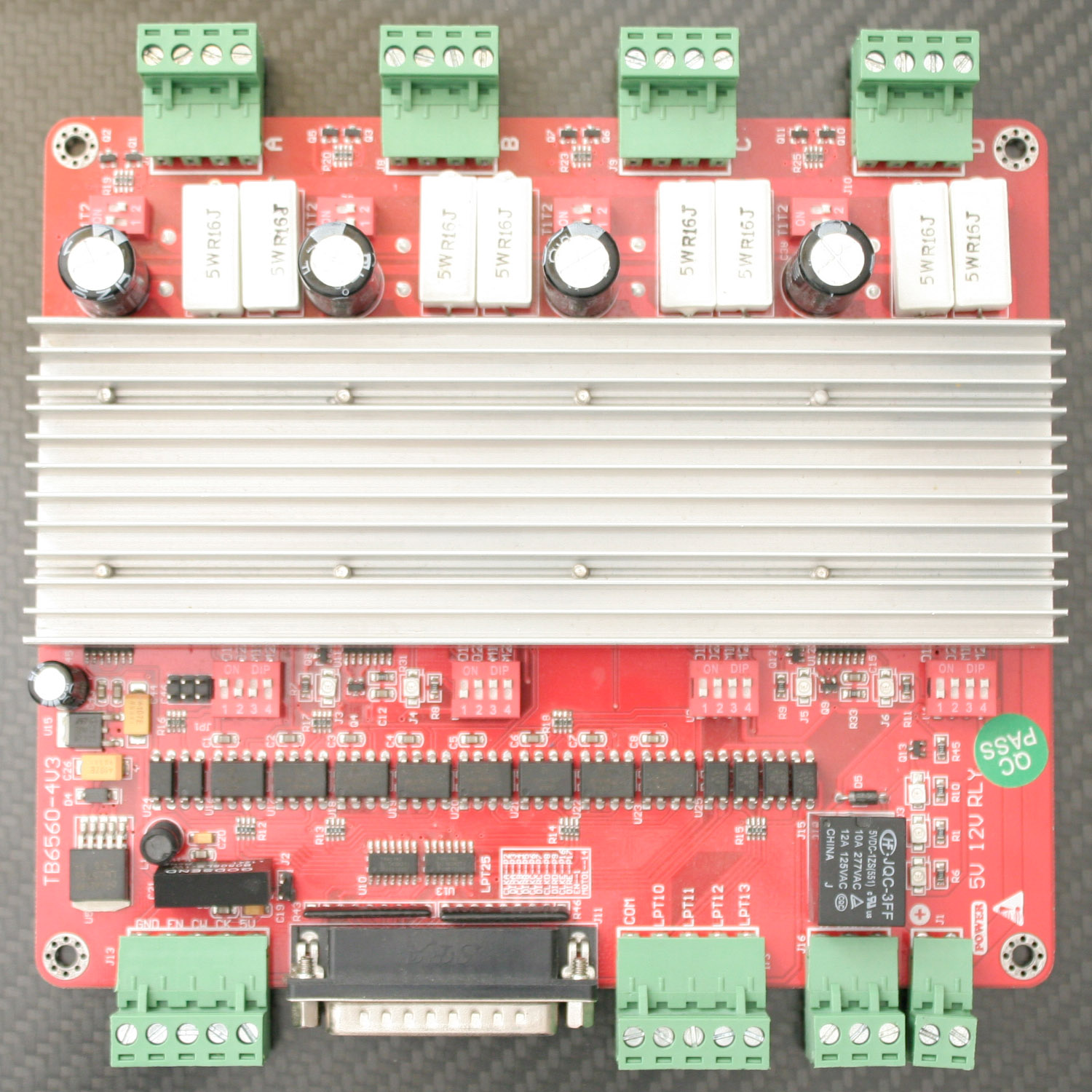
Toshiba TB6560AHQ
I may admit I did not expect much from the cheap, red ST6560T4 driver board with four Toshiba TB6560AHQ 3A motor driver channels, but it’s a great driver IC and it did perform surprisingly well. The drivers were set to 2.25 A for this test and achieved a good linearity throughout the microstep sequence with a deviation of ± 2 microsteps when unloaded.
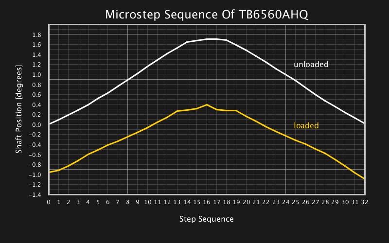
There were, however, reproducible non-linearities at the upper full-step position which the A4988 did not show, and the TB6560AHQ’s behavior under load differs noticeably from the idle behavior. Also, it’s surprising that the motor is deflected under the load by more than a half full-step, since the higher current should increase the motor torque similarly to the DRV8825.
Conclusion
I hope this write-up and measurement results help you with your design decisions and when working with these very common drivers. I did this tests for a rather narrow application, and they shouldn’t be generalized too much. Although I dare to conclude the following:
Stepper motors in heavier machines, such as CNC routers, that use open-loop microstepping, mostly benefit from the reduced vibrations and the lower torque ripple of microstep mode. They can not rely on microstepping as a means of increased positioning accuracy (at least not without keeping large torque margins), since a load may still deflect the axis’s position by more than a full-step.
However, small and light applications with low load and low friction may indeed resort to microstepping as a cheap trick to squeeze more accuracy out of a standard stepper motor. Even with a cheap, low-current motor driver, looking at the very well performing A4988, accurate angular positioning is possible, as long as the load is kept low, ideally within the incremental torque of a microstep.
As always, I’ll be glad to hear your thoughts, opinions, and experiences on the subject of this post. What’s going on with my DRV8825s? What stepper motor drivers do you rely on most of the time? Let us know in the comments!


It looks like you used different current settings for each of the drivers. Usually a stepper will perform significantly better when its maximum current (without saturation) is matched to the driver. This (from experience) can then be tweaked for either more torque or more accuracy, but usually It is a trade off one for the other.
You’re right, kind of. They were all on the maximum current that they would deliver without heatsinking – on the same motor. Saturation is not a big deal in a static test, and between 1A and 2A there’s not much going on with saturation anyways. It’s _probably_ fair enough. The alternative is testing each driver on a different motor, which comes with other problems in terms of comparability.
Awesome writeup. Beautifully done with all the extra care you took to ensure consistency and reliability of the results.
Yah, thanks for documenting something I had a suspicion about, but lets face it, was probably going to be too lazy to go into myself….. until it frigged me over in the middle of a project.
More articles like this please!!
Yeah! It’s good seeing science relative to the community being done. Some of the half-arsed re-writes of articles from blogs that pop-up on HaD get tedious, but well written articles that could help with part selection are always welcome.
You’re new here, right? “Half-arsed re-writes of articles from blogs” _is_ Hackaday for the first ten years of its existence.
But we’re glad that you like the original content stuff we’re doing nowadays too. :) And editorially speaking, I agree that this is an awesome article.
Another factor is the driver voltage, as a 24v micro-stepping driver should perform slightly better than the popular 12v supply versions.
Empirical evidence is always welcome. =)
Voltage improves stepper max speed because it shortens the coil charging time. This test was done at 0rpm so it should not be a game changer here. Current adjustment, however will definitely impact deflection with the same motor and load.
I tested them @12V, but Momus is right, voltage isn’t much of an issue in a static test.
I have been testing the DRV8825’s on and off for the past few months. (Read been pulling them out of the dust bin and trying different configurations every once in a while). What I found is that these drivers do not like anything past 24v at full 1/32 microstepping even though they are supposedly rated for 36v. For the best performance so far I have run them at 32v in 1/8th microstepping manner with active cooling and tuned them down to about 1.8A, not the full 2.2A. Internally these drivers (brand name or generic) suffer from thermal shut down at higher voltages and no ammount of heatsinking or forced cooling helps them, I am also aware these are supposed to heatsink to PCB which made me put them on risers and sink the bottom of the driver(PCB). With that said, these drivers in the configuration mentioned above put out some nasty torque through even small NEMA 23’s. Figured I would throw the voltage variable here, or at least my findings. Maybe I am shooting in the dark with these but plan on using them on a small mill I am building, if these dont work out I will upgrade to the toshiba drivers. ~7bux per axis is not bad.
I seem to recall an app note for the Allegro chip that mentioned the relatively high micro-stepper switching frequency (+1/16 mode) could be problematic at lower voltages.
Its odd that your chips borked in low-noise mode, but the DRV8825 have a bad reputation with many users.
We use a modified RAMPS 1.4 at 24v with the A4988 modules in 1/16 mode on our 3D printer.
The Marlin firmware does a few tricks to get around the initial-stall problem too.
The results of the drv8825 are indeed quite bad. Were you able to reproduce this behaviour with other drv8825 drivers ?
But more importantly, it looks like the load deflection is roughly 1° here, which is a little bit more than half of a physical step, (or 8 microsteps here) assumed it is a 1.8° per step motor that was used.
In a real cnc router, then the rotor would probabily move up to 1° in either direction, because the load will change both in value and direction. So, 2° accuracy, ballpark.
Since rotor load deflection is one order of magnitude more than theorical microstepping accuracy, I’d say that microstepping is useless for CNC router precision. For lathes or 3d printers (depending on the design), load direction might be the same, so I wouldn’t be so sure.
But even if it is not good at improving precision, microstepping is very effictive at reducing vibrations, and that alone is a good reason to use it.
Could you try to vary the load up to stall torque to see how much it deflects before loosing a step ?
Yes, as said I repeated the test with multiple drivers from multiple sources.
Good write up. I’d be interested in seeing a comparison of some commercial driver boards and larger nema frame sizes
I can confirm the “jump” behavior of DRV8825 driver.
Thanks! Good to know! What breakout board/driver board were they’re on? Pololus?
The 8825 is well-known to skip microsteps with low-inductance motors in mixed decay mode. Causes all sorts of ripples and crunching noises in 3D printers. You need to switch it to fast decay mode if you want proper microstep spacing.
The problem is that the PWM chopper’s minimum on-time (blanking time) is way too long, which allows the coil current to rise way higher than it’s supposed to on certain microsteps. You can plug the motor specs into my stepper driver simulator to see for yourself what the coil currents are doing: https://github.com/rcarlyle/StepperSim
Ryan, I just checked out your Excel simulator. That’s an amazing piece of work and explains a lot of what we’re seeing here in the test. Thanks for making these available!
Hi,
Stumbled upon this while generally searching around. I starred your Github repo.
thanks
Ultrasounder
Great article!
I wonder how well the Trinamic TMC2100 from the ‘SilentStepStick’ fits in here?
Thanks! I’d be curious about this, too. Unfortunately we couldn’t test them this time. If I can get my hands on some I’ll test them.
Also try the TMC2130s. It might not be enough of a difference but stallgaurd 2 might change things.
Hi Moritz, you can contact me via eMail, then I send you some TMC2100 and TMC2130 based drivers for testing.
You can use the support eMail address.
http://www.watterott.com/en/Contact
Thank you Stephan, I just wanted to offer, that I send some drivers…
I am pretty sure, that there is no difference between TMC2100 and TMC2130, as the way he microstepping is done is exactly the same.
Hi Stephan, thanks for the offer. I already bought some for deep testing.
Very nice. Something I always consider when microstepping is that you need to maintain full power to hold position. Some applications like to move the motor, then power off. A stepper will cog to the nearest full step if you used microstepping to get to position. It is advantageous to be able to move and power off in applications where heat dissipated by the motor is an issue (like precision optical instrumentation). For some reason nearly everything I build with steppers only powers up the motor when moving and powers down on reaching the target.
Probably goes to half current to reduce heating. Turn off the power would have the motor freewheeling.
No, they don’t freewheel. Steppers have an amazing amount of holding torque (try turning a shaft by hand sometime if you never have). Everything has its limits of course, but if you are moving small things, the motors magnetic cogging does just fine to hold position. We do it all the time. And any gearing multiplies the holding torque.
That’s pure detent torque and it’s quite small (relative to motor output), so unless there is no load on the shaft it’s better to keep them energized.
A better approach will shorten coils instead.
Hi, would you be able to share the design of the fixture (stl). This allows others to repeat the tests under “comparable” circumstances.
Here you go!
You do not “script” in Java, Java is a compiled language.
Compiled into bytecode. Just like perl, python, ruby….
He’s right, but has he ever been to Java?
Do they script in Java?
Never!!
Java is a programming language, as all programming languages it can be interpreted, compiled or a mixture. The default (and most common) Java design compiles to bytecode which is then interpreted or compiled.
However that is irrelevant to the other point: scripting languages can also be interpreted or compiled. In most cases one have to look at the usage pattern of a certain language to see if it is a scripting language – but even that isn’t enough: applications have been developed in scripting languages and scripting have been done in C, C++ etc.
There are no sharp borders.
Sorry: I absolutely cannot resist:
https://imgflip.com/i/19r6ve
It doesn’t help that there’s a language called Javascript!
What did you set the Decay mode to on the Texas DRV8825? I found this made significant differences and I had to add mod wires to the driver boards to set it to FAST. I’d be interested in seeing the results with DECAY tied to 5V.
+1 to this.
The decay mode has no effect on this. Anyways, it’s on auto.
Thats NOT my experience. It’s the decay mode setting that causes the big “step in the middle”.
Yes, “AUTO” is wrong. Auto works well if you run a 3V stepper at 3 or 4V. But not when you run a 3.1V steper (current limited) at 12V (as is normal practise)….
Nope. Set it to +5. Microstepping without it set to +5v is very poor. Been there got the t-shirt. This is well covered on the net. Unfortunately most modules don’t bring the Decay pin out so you have to get a wire onto the pin of the chip.
I don’t think that the decay mode will alter the results of a static test, but I will try this. Thanks for the hint!
The fixed minimum on time together with slow decay and a high supply voltage cause the current to become higher than the setpoint…..
Great article by the way!
Any chance you could run the same test with TMC2100 drivers like the SilentStepStick in its 1/16th microstep to 1/256th microstep interpolation mode?
I don’t know what to make of this. I thought you only made sponsored product placement articles and now you rank the TI driver worst in your test while there is TI adds all over the place?
Oh, I’m so confused now..
Sorry. Here, take this TIssue.
[slap]. No!
+1
Haha, win.
I am running DRV8825s Since Pololu advertises them as a high current, low heat drop in replacement for an A4988. I was/am a newb to these electronics and don’t really know any better. I have had a slight ripple effect on my 3d printed parts I have never been able to diagnose, at first I chalked it up to frame vibrations, then I learned a little better and blamed my Z rods, but even after switching to high quality lead screws It is still there. That awful looking graph might explain it…I probably won’t replace them or anything, but I will certainly remember this when building my second printer.
It’s a common problem with 8825s. Switch them to fast decay mode or swap in 4988s.
Very good write up & testing! Another thing to consider though are the other limitations imposed beyond the electrical ones.
Manufacturers also typically list the mechanical accuracy of the stepper motor in the datasheet. This is usually based upon the accuracy of the mechanical assembly as opposed to the electrical theoretical accuracy (detent torque vs holding torque as given above).
Most stepper motors I’ve seen (usually for CNC applications) don’t have a mechanical assembly accuracy of greater than 5% per step (or about ±0.09° for a typical 200 step per revolution motor). So basically the mechanical degree variation within a full step varies from 1.71°-1.89°. Any electrical accuracy claimed beyond this limit becomes superficial as your mechanical error is greater than what you could electrically provide. If a driver is providing accurate and smooth 256 micro-steps per step, that’s great and all but if the motor can’t physically achieve that same accuracy around the entire motor any gains in accuracy you achieve electrically are lost in the mechanical ‘noise’ threshold and are essentially meaningless.
Electrically this means that a mechanical limitation prevents greater than ~4000 micro-steps per revolution in a typical stepper. This is equivalent to 11.111… micro-stepping mode. Since micro-stepping is provided in integer values and 11 micro-steps isn’t typical, the closest typical value is 10 micro-steps/full step. Any micro-step value finer that this exceeds the accuracy that the manufacturer can provide mechanically between the individual steps and thus relying on accuracy beyond 10 microsteps/step becomes lost/superficial/meaningless.
Unless you can find a stepper with greater than 5% mechanical accuracy that is, then just redo the calculation based upon the mechanical limit of that stepper and you can find at what point electrical micro-stepping is helpful for your particular motor vs advertising fluff of the motor driver.
Should also say, this only matters for improvement of stepping degree accuracy. Micro-stepping is awesome for dealing with vibrations.
Are you saying the shaft won’t rotate between the 254th and 255th microsteps? That seems hard to believe, assuming you had enough current. If you have some kind of encoder-type full-circle detector, and you run the motor always in the same direction (thus assuming backlash is not present or affecting results), are you saying that from the SAME starting point (as reported by some optical beam-break or whatever encoder I mentioned we were assumed to posses), on successive movements from microstep 254 to 255, you would get a variable amount of shaft rotation? Seems like if there were no bearings in the motor, other atomic-scale wear through a rotation, things should be setup pretty darn similarly each time. Or would we still be seeing run-out related effects then?
The point is that the mechanical manufacturing accuracy of the stator/rotor is such that the full steps vary in angle up to 1/11th of a step, and therefore the microsteps can be off that amount as well depending on where in the rotation the motor is.
It’s the same problem as using cheap threaded rod instead of proper drive screws. The thread pitch is variable in the short scale, even though the rod may have an exact number of turns per foot.
Exactly
Your answer ignored all of the assumptions I setup. To be more clear, I care about repeatability. I guess you get what you pay for, and I’ll have to do my own tests.
Slo-Syn makes 5% and 1% accuracy rated steppers. On my lathe conversion I have a big Slo-Syn stepper with 5% accuracy, connected to a 16mm/turn ball screw through a 2:1 cogged belt reduction.
Half stepping will give plenty good enough precision for what the lathe will be used for.
This guy solved the problem with the DRV8825 by using 4 diods in series with each phase! Great write up: http://cabristor.blogspot.se/2015/02/drv8825-missing-steps.html?m=1
Woah, that’s an interesting workaround. Great stuff!
Or just switch them to fast decay mode. Seriously, it’s a known problem with the mixed decay mode algorithm on the 8825.
If you read the post, you’ll see why they didn’t use fast decay… because it hurt the person’s ears
Yes, fast decay hurts my ears too. Depends on how old you are / how much hearing damage you have :-) Also, Deltas don’t have issues with 8825 noise because none of the motors sit still.
you could just stick a power resistor in series (or use long thin wire), like in the olden days when using a current limiting resistor instead of a switching mode driver
No, this is not the same. The diode gives “fixed” voltage drop, the resistor’s is dependent on current. But this is discussed more in depth in the linked article. You could read it.
Great info, thanks!
Hi, I’m the guy that wrote that article. Arrived here by following the analytics of the post, and I just wanted to share that it’s really satisfying to see that you found it helpful. Thanks for the recognition!
Pedro, excellent detective work!!!
Your “AAAAAAGHGH!!! What the hell is that?? pain in my eyes!!” graph approximates the measurements for the DRV8825 very closely, I would suspect that the solution you provide in your article would make that driver’s behavior look way more smooth/expected..
Awesome work!!
The graph of the DRV8825 looks awfully familiar to me…. I measured that curve on an A4988! The issue was that it was configured wrong. Some strapping on the “stepstick” was wrong, resulting in the one very big step near step eight. I patched a few of those A4988 modules to behave just like you measured. So… IF you didn’t mix up the measurements of the two modules, then the 4988 can behave just as bad as the drv8925 you measured. And probably you can get the 8825 to behave just as good as your measurement of the 4988.
More details would always be welcomed.
I was just reading about this very thing in the past few hours. I’ve had to compare rack and pinion, micro-stepping, direct drive and gearing. Lots of things to consider to be certain.
I assume you used dy/2 in calculating the shaft angle changes? Just out of curiosity, why not mount the laser on the shaft? The factor of 2 made it easier to get an accurate read at 6 meters? Every LSB helps.
Yes, I did. Using a FSM on the shaft and having the laser static doubles the optical lever, making the readings more accurate (angle of incidence equals exitangle). But sure, you could mount the laser on the shaft and just throw it over twice the distance.
Pretty interesting. Makes me want to do a DIY controller with current amps and14 bit DACs and see what happens if you calibrate and keep a current table. Also makes that project with the encoder on the stepper motor look even more interesting. Huston instruments small plotters used steppers. HP small plotters used DC motors and encoders and they were mush faster and more precise. A convenient closed loop on a good affordable motor is going to be a break-out product one of these days.
Is there any error present if the mirror isn’t exactly across the shaft, and the laser isn’t pointing exactly at the centerline?
Shouldn’t be.. the interesting angle is the same for those cases. Just draw it on a paper for yourself to see.
Great write-up – I’d love to see more of this sort of thing.
Especially good ways to build test fixtures, like how would you test different kinds of linear rails under a range of conditions?
One suggestion on the graphs above: can you add an “ideal” dotted line? It would show the deviation a little better.
I have to rank this as one of the best articles I’ve ever read on HaD. Which should be taken as a very strong compliment. My undergraduate degree was English. However, this is slightly biased by receiving my A4988 drivers today. The DRV8825s came a few days ago, but I’ve not opened either package yet. I’m still mostly trying to come to grips with the Arduino world in order to work with kids. At least until I introduce them to better architectures ;-)
The datasheets have quite a bit to say about choice of decay modes that I’ve not yet deciphered, but this has given me a good framework for sorting things out. The rules struck me as pretty complex.
FWIW The sensor array from a scanner would make a good target and would simplify the evaluation process modulo reverse engineering the interface. Particularly if you put a slit on the laser.
I look forward to reading more of your writing.
Kudos to all commenters!! For me, there is almost as much valuable information in these comments than in the posting itself. Thanks to all for your additions to this most informative post! This post, all comments as well, now headed to myHD. Good stuff!
Microstepping accuracy, in addition to drive design, also relies on having a stepper motor designed to do such a thing. If you think about it, there’s no good reason why a linear change in phase in two adjacent steps necessarily corresponds to a linear change in angle. Unless a stepper is grossly mis-manufactured (stators are not identical), you can imagine the half-step to be accurate by symmetry – but beyond that, the angle-to-electrical-phase correlation is usually not linear, unless a manufacturer has specifically designed the stator and rotor geometries so that this is the case. Unsurprisingly, most non-precision, cheap chinese steppers (which are great for most applications) probably aren’t going to do too well in this area, and the manufacturer probably don’t even realize that this is a design parameter (unless, of course, they’ve really painstainkingly, mindlessly copied a well-engineered one down to the nuances of coil shape and tolerance)
If it’s any consolation, the Wantai motor brand used here is a relatively commonly used in DIY 3D printers and it appears to stack up pretty well. There are known reputable, inexpensive motor sources that the more discerning builders can buy. The people buying cheap kits or cheap machines might not be getting the decent ones, but sometimes there’s something to be said for “you get what you pay for”.
so can I be an ass and just ask what microstep everyone is using on they’re drv8825s? My use is: a mpcnc but I use a cnc usb controller board and drv8825 drivers combo instead of the usual ramps. electronics are from buildyourcnc.com.
Really enjoyed this write up. Keep up the good work.
Awesome to see these results so clearly. Would be interesting, as well, to see a plot of current alongside these graphs. But, I have a feeling an averaged current reading at each (stationary) microstep would be somewhat irrelevent (as suggested, as well, by others’ comments regarding decay-periods, etc.).
Recurring thought: It seems like there are quite a few knowledgeable folk on this matter. Why, then, are we still using motor-drivers that pretend each microstep is identical…? (“step”/dir inputs). Why hasn’t there become somewhat of a standard to use full-steps for *position* and microsteps merely as a means to traverse from one to the next (reducing oscillation, etc)? Sure, e.g. for a 3D printer, the “resolution” would decrease, but having seen the results of poorly-implemented microstepping on parts (wasn’t there an article on that recently?), I’d think the “pixellation” caused by full-step-limited edges would actually be smoother (or at least more accurate) than the randomness caused by microstepped-edges.
…And certainly there are cases where that accuracy is more important than high-but-random-precision, e.g. printing traces on a PCB at right near the minimal-full-step-tolerances for the stepper… E.G. Drawing parallel 45degree traces with only a single full-step step separating them (on the horizontal/vertical). With full-steps would result in a stair-step pattern that’s matched on each trace, resulting in clear spacing between traces (albiet also stair-stepped). But doing the same, presuming that microsteps *are* steps (step/dir), has dramatically different results, as shown in the graphs, depending on direction of approach, etc.. Overlapping traces are definitely likely… Thus *dramatically* decreasing the resolution.
How does a dynamic result compare to your static test result? Motors don’t usually move a single microstep at a time from a dead stop to a dead stop. The rotor is normally in motion with controlled acceleration. The rotor’s inertia has to have some effect on the final position. I think a more realistic test might be to spin the motor one rev plus one microstep then stop, then do it again for 1 rev plus two microsteps, etc., all under controlled acceleration.
I’ve looked mostly at (static) positioning accuracy here. At low speeds, accelerating and decelerating turns the rotor’s inertia into a load momentum, which affects the momentary positioning accuracy in the same way as in the static test.
But of course, there are dynamic factors which static test results cannot sufficiently reflect, like the influence of decay modes, supply voltage, and magnetic saturation. At low RPMs, you may get away with the static considerations, but with increasing RPMs, these dynamic factors will also increasingly come into effect.
Once I designed a system with 3 phase steppers and microstepping. The driver consisted of ADCs, current sense amps and comparators for hysteretic current control. The goal was moving a mirror with as little vibration as possible. So there was very little static load, mostly inertia. In static or low speed this worked quite good. But with higher speed – and therefore higher inertial load the vibrations reappeared. Although the currents were still precise and sinusoidal. We had no other explanation than imperfections in the motor. On the other hand there were for sure ‘imperfections’ in the finances of the company which ended the project soon after.
Nice article, very well explained. Nowadays it is kind of easy and affordable to use field oriented control with steppers. The result is a high performance servo drive with high torque due to the stepper design. The only thing you need is a cheap encoder (magnetic for example) and some microprocessor running the foc algorithm. Hook it up to a bunch of drivers (one for each coil) and enjoy a great solution.
good article
Wow. Thanks for that post. Very usefull.
Would be interesting to perform the same experiment using the DRV8825 (and other chips) on the manufacturer’s reference board.
Is this a limitation of the Pololu driver board rather than the IC itself?
Just look at the size of the board. There’s very little copper area there, so thermal performance is intrinsically limited. And it’s tricky to set and to measure the current set point or to modify the decay mode setting, all of which are valuable parameters to control and vary in this experiment.
I cannot say anything for the DRV8825, but the A4988 has a “bump” around step 8 and 24. This is caused by a pulldown or pullup not being strong enough on the Pololu driver board. Causing some mode to be wrong or something. (sorry, I’m not strong on details here)
Our electronics guy recently discovered this in the Ultimaker2 electronics, which is pretty much a copy of this driver design but then 5x on a single board. As we where seeing this slight inaccuracy as well. (yes, the quality of the microstepping is visible in 3D prints)
With the A4988 on >12v PSUs, you need to SHORT the ROSC pin to ground to force it into low-current microstepping mode. The Pololu default is a pull-down resistor, which puts the driver into regular mixed decay mode.
Likewise, on the 8825, you need to pull up the decay pin to +5v.
Pololu’s settings suck for 3D printers. Everybody but Makerbot copied them years ago and never thought twice about it.
I’m gathering it is a configuration issue, though I’m not a fan of the stamp-sized stepper driver modules, they are harder to keep cool.
In short, it’s a matter of setting the driver configuration, at least the decay mode to match the motor (coil inductance makes a difference) and the use (high speed, low speed, etc.).
The problem is the motor specs being outside the range the chosen decay mode can handle at that drive voltage. The simple decay algorithms used by these cheap drivers can’t handle a very wide range of motor specs. You have to set the appropriate decay mode for the motor. The Pololu defaults are for “slow” motors with higher inductance, whereas most people these days run “fast” motors with low inductance.
In more rigorous terms, the driver’s blanking time is too long relative to the amount of decay time provided, causing the coil current to overshoot and then not get pulled back down before the next on-cycle.
You should consider changing the title , as well as some of the descriptive test on the situation you are testing to read (“how accurate is microstepping with drivers that have an important missing hardware component”). All of the drivers you tested suffer from an important missing hardware component/s that drastically improves microstepping performance. Read the datasheets!!!! RTFDS!!! Especially true for the DRV8825. I will leave you to figure it out , and rewrite your article , as it has little to say about the true performance of microstepping without proper hardware that most datasheets will show you is a requirement when running a stepper above its rated voltage (which is nearly always the case).
It’s incredibly presumptuous to demand an article rewrite like that. I don’t think it’s fair or reasonable to put the onus on driver module design on the writer. If anything, the blame should have been put on those that designed and built the driver module.
On top of that, most driver modules of the type used don’t expose those configuration options, Watterott’s Silent Step Stick (not tested here) is an example of an exception.
Would you be willing to clarify for us hobby-types who could use some guidance in which modules might be better than which other ones?
I read datasheets if I DESIGN something. If you know a design issue of these boards then write it in this comment. This words ” I will leave you to figure it out” are just very rude behavior in this context – you make yourself look like an as…le.
Nice writeup of a useful topic, especially after a suicide test?? :-)
https://hackaday.io/project/7814-sweet-dreams-cnc-multimachine/log/25897-the-suicide-test-episode
Great article! Thanks for doing the testing and the write-up.
So the error from microstepping is shown, but does that error go back to 0 or at least improve when the driver gets to the full-step position?
And it would be great to see the comparison of errors between microstep sizes. As in, show the errors of 1/8step, 1/16step, 1/32step, etc for one driver.
Yes there error is zero (or as good as the motor mechanics) every fullstep/halfstep, the errors do not add up
1/8step and 1/16step is just skipping some of the steps in 1/32step, the drive is the same
Indeed a nice test, giving quite some insight.
However, I think the conclusion drawn isn’t correct. Especially this part:
“They can not rely on microstepping as a means of increased positioning accuracy”
Looking at all three diagrams, I see this:
1. Applying a load deviates the motor shaft from its intended position.
2. Each single microstep moves the motor (ignoring these DRV8825 quirks).
3. The deviation seen with 1. is constant.
4. Movement distance per microstep is pretty exactly the same, with or without load.
5. Movement distance is reasonably exactly 1/16 of a full step on the two better drivers.
Putting 2. to 5. together, the only conclusion can be that microstepping _does_ increase accuracy. Accordingly, one can simply scratch this whole ‘incremental torque’ theory, because it has no influence on the motor position.
Part of the confusion around microstepping is perhaps the assumption that a stepper motor holds exactly the intended position. As we see, it doesn’t. Depending on the applied load, actual position can deviate +-2 full steps from that intended position. And these +-2 steps hold true for every single microstep position. After doing 4 microsteps it doesn’t become +2.25/-1.75; it’s still +-2, around that new intended position.
And that’s why there’s an increase in accuracy. The indended position moves, the range of the actual position around that, too.
Good point, your reasoning is correct, but I don’t agree with this terminology. Positioning accuracy is not a statistical average of measurements, it’s the expected deviation from the target posisition. Imagine you want to machine a precision part from aluminum: you can’t just machine ten pieces to make them more accurate.
I’d bet that deviation between intended and actual position isn’t random, but depends on a) motor load and b) motor current. The higher the load, the higher the deviation; the higher motor current ( = available torque), the lower the deviation.
Setting the usually well known and constant motor current/torque aside, actual position becomes unpredictable/random/statistical only if motor load is unpredictable. This certainly applies for milling machines exposing a noticeable stick-slip effect, high carriage friction or high loads due to the cutting tool. It does not apply in other applications, like your measuring mirror (constant, known load) or a 3D printer (loads almost only due to acceleration).
It also gives good hints on what to improve to gain accuracy: reduce motor load (e.g. by gearing), make motor load more constant, increase motor torque. Perhaps even advanced technology like predicting motor load in the drive controller and adding or removing a few microsteps according to this prediction.
That said, I don’t want to talk against closed loop systems here. Steppers have their limitations, so closing the loop undoubtly makes sense when needed.
I would add, that microstepping also adds stability to torque for stepper motor.
As second I would like to add that absolute holding torque is the same (as my understanding is). The reduction of holding torque is just in relation to next microstep.
I get the same idea
Is there any advantage to microstepping as opposed to using gears? Aside from size and the number of parts.
Gears will be better, because you will get more torque.
Microstepping can’t replace gears. But even if your application requires them, you’ll probably want to use microstepping anyway to reduce vibrations, torque ripple and overshoot. If your application can live without gears, microstepping is practically free, doesn’t wear and shows very little backlash. I’d say it depends.
Also not previously mentioned, but gear reduction also reduces your top speed by the reduction ratio, on top of the mentioned backlash issue, which can easily exceed the positioning error caused by problematic microstepping. Better to mod the driver for better handling, a lot of drivers are apparently not configured optimally for their use or the machine they’re in.
Microstepping also reduces your top speed if you are bound by how quickly you can deliver pulses to the driver. if Arduino’s AccelStepper recommends 1000 steps/sec max to deliver 300 RPM on a 200-step stepper, x16 microstepping would require 3200 steps/rev to give only 18.75 RPM.
Thanks.
Hey, thanks fpr the article. Since its a very compehensive experiment, it would be a good idea to build a comutating device yourselfe (implement the microstepping algoritm in an mcu). This way one doesnt need to rely on blackboxes like drv8825, although its faitly well documented.
I have to say I am suprised about all this open loop stepping motor usage festival, encoders are really cheap this days and I dont think its worth the hussle not to use them in high precision applications.
I wish there were more arti les like this on hackaday.
There are several closed loop projects. The problem being it adds complexity and cost. Generally more wires, more connectors, more components on the controller board. Then there’s complexity in the firmware. Someone would have to tune the control loop to the machine as well. If you’ve had difficulties tuning the heater PID, or tuning your accel & jerk settings, imagine tuning servo loops.
I think it will happen eventually though.
In the company I work for, I have been developing a stepper motor driver (from scratch) for a while. To bad I cannot make it open source, as I would really like that. In that project from the very beggining I am using linear pr rotarry encpders with stepper motors. My alghoritm doesnt even have open loop functionality workng yet, as we havent used it so far for anything. Thats the reason why I was so suprised that so many people in the community use open loop- for instance I never had a problem with steps loosing or position loosing, the PID corrects everything. You say closed loop is more complex, but when you look at this from another level, like what are the cons and advantages in the end, then it is more difficult to make a working open loop system.
You see, while you were developing your driver, we were all running our printers already :-) So it can’t be that difficult to get this working. Certainly not more difficult than wiring up a closed loop system. And much cheaper, of course.
The trick to get this running reliable is simple: avoid overloads, even momentary ones. Have proper acceleration, motor current well adjusted and everything is fine. Not a single step loss after running hundreds of hours high speed here.
In the end it all comes up to the resolution of movement. We needed 1 micron (XY movement of arms, without negative ratio gears, only using belts). Besides that you showed in this article that you cannot trust the motor to make a certain microstep, also you cannot ignore the fact that the torque can change in time because of various parts using out. Also a person can interfere into the moving area. Im am not saying any of this is wrong, its great to see that certain things are possible. But at certain point you need the closed loop, which in my opinion is not an expensive solution.
Wait, you’re filing a 1 micron requirement with a belt drive system? How’s that working out?
Better or worse to be honest. Its a work in progress. The point is with a closed loop with an encoder of 0.4 micron resolution your pid controller is able to oscilate very closelly to desired position.
You’re not wrong but I think there’s realities that you might not be attuned to. Hobbyists work on what they want to work on, and there’s only so many people into CNC/3D printing, etc. that also have the skills to work that kind of system. We also seem to be in a market where $10 extra cost to the machine is simply intolerable. The 3D printing hobby as it were seems to strongly favor the RAMPS board, which is obsolete and a known fire hazard because they won’t spring an extra $20 for a better board.
I get the idea, I also understand that 3D printer enviroment doesnt have that much of a load changes. It i true that in a industrial application sometimes people tend to pay to much for “reliability”. I try to stand in between.
Meh I understand why servos cost so much money as it is. People buy wong-xu-long steppers on ebay for 8 bucks shipped and expect them to have sub-micron precision, meh. Gear reduction on well machined components will easily get you an order of magnitude of resolution increase per bull-spur set with good, precisely machined components (i.e., none of that sintered metallic or injection molded plastic – get your stack up from Boston Gear) properly hobbed, faced and balanced gears will let you step predictably enough that you can store the rotational inertia (pun not intended haha) in a look-up table (or if you’re alright with waiting forever, find out how much is just enough torque to step the last gear of the train one iteration, then wait till the remaining energy in the system has dissipated to shear loss and step. Or use linear rotary encoding systems. Or just close the loop, which is the right way to do it. Anyways, This project http://hackaday.com/2016/06/01/mechaduino-closed-loop-stepper-servos-for-everyone/ closes the loop.
“the best we can assume is that the motor will be somewhere ± 2 full-steps (yes, that bad) near its target position, which is the maximum deflection before the rotor snaps into the wrong full-step position, resulting in step-loss.”
This sounds rather strange, as how can you move the rotor with external torque over half a stepp without it snapping into the next step?!
This goes against all I know about magnetits and motor design.
I agree that this is weird. Motors have a basic positional accuracy spec of 5% per step, noncumulative. How can the thing be off by two full steps and still be useful to make a precision machine? This whole test smells fishy to me. I don’t think you can extrapolate dynamic performance based on these static measurements.
A full cycle goes over not 2, but 4 steps. Two coils are magnetised in both ways, 2 x 2 = 4. Exceeding half of that makes the motor snap over.
That said, these +-2 steps are a worst case scenario. Available torque is already exhausted. In real world applications, stepper motor torque shouldn’t be pushed to its limits, so positioning accuracy is better, too. If the carriage needs 50% of available torque during acceleration and 10% during constant speed movement, accuracy is +-1 step during acceleration and +-0.2 steps during constant speed or while holding position. That’s why 3D printers and light duty CNC mills usually see a lot of a better accuracy than this theoretical worst case figure.
This +-5% figure is an entirely different thing. That’s deviation due to dimensional inaccuracies of the motor and has to be put on top of all the figures described here. E.g. it reduces this +-2 steps number to +-1.9 steps. Which doesn’t mean that the motor becomes more precise; it means that the motor might snap over earlier, at 5% less load.
This is a stimulating piece of work. I am reminded that several decades ago I used an Acorn RISC PC and ARM assembler code to do similar experiments – using the code to generate intermediate PWM steps and measuring angles. Then integrated chip sets came along so no-one did it themselves, but this article shows the pitfalls. Always keen on back-to-basics, so perhaps this project can be extended to using Arduino or ARM microcontroller PWM outputs and driver FETs to measure the responses of different setups and motors.
Yes this is also what I meant. Using ready chips you are quite limited when doing full range tests.
Hi Bremen
Apologies – I hadn’t read through all the comments, so I didn’t see that you had been doing the same sort of thing commercially. I worked in a university research dept., so the experiments were not of commercial interest – more about “fun things to do with a Risc-PC”. I dont remember much about our results except that typical step motors were very non-linear between full steps.
You are right about this, I have noticed (tested with a scope) that even though the windings are suplied with sin and cos current, they tend to not always follow the position in time. For a certain RPM, prrcision and load however, they work quite good.
So it would be better to use a gear/pully arrangement to achieve micro stepping ?
Ie16:1 toothed belt and in full step mode. Will give 1/16 step per full step with full torque/ accuracy ?
In theory yes, it is better to use full step and a mechanical negative ration in my opinion for the sake of the torque. But as it has been pointed out, with full steps the rotor will oscillate a lot more than with using microsteps (16 times less however because of the ratio).
I wouldn’t do that, I think your results would be worse, and you reduce your maximum speed by a factor of 16.
If you’re using 16 tooth drive pulleys, then you would need 256 tooth pulleys. If my math is right, that would be a 163mm diameter pulley.
Well, the smaller pulley or whatever doesnt necessarily have to have 16 tooths. It can have less as long as the 1:16 ratio is right. You can get really small “one block” gears that are even 1:100. As for the speed you are right, unless its not a factor.
16T is the smallest GT2 pulley I’ve found with a 5mm bore, b/c 5mm shafts is common with NEMA17 motors, so alter the numbers based on whatever differences with the system you had in mind. It’s a commonly used size pulley for 3D printers, so that’s why I used it. But even with 10T, you’re talking a 100mm driven pulley to get 1:16. Adjust that OD relative to the tooth pitch if you had some other belt pitch in mind. It would make a great spectacle, but I question its usefulness.
I didnt have any particular device in mind, I also reffered to pulley as an abstraction gear element. Sorry If I understood the concept wrong. You can get a very good ratio on a planetary gear and its really small as well. I didnt mean for anyome to build a 1:16 ratio physical system on an actual levers or belts. sorry.
Interesting article, and nice test setup! We would like to point out that while you refer to the boards you used as “Pololu” products, the units shown in your pictures are not from Pololu. Your tests are primarily of the underlying chips on the carrier boards, so it is unlikely that your basic results would be any different on our boards, but counterfeits and knock-offs can vary in their quality. Please hold unscrupulous sellers accountable if they deceptively sell items as “Pololu” products when they are not. And in cases where you consider a cheaper knock-off, please think about how you would feel if you put effort into developing and supporting products just to have your prices undercut by people who indiscriminately copy your designs, pictures, and documentation. Ordering genuine Pololu products also supports our continued development of new products.
I understand your concerns. The test focuses on the performance on the underlying ICs and included Pololu boards, but unfortunately, I chose the ones for the photographs by the looks. My Pololus are already quite abused (and therefore loved). Sorry if they don’t show genuine Pololus – you’re probably the only one to notice.
Below the disc loading tray is often a LED light indicating when the Wi-Fi is
at use. Blu-Ray Dv – D players consist of: ~200$ – ~600$ Once more influenced by brand,
and when they come having a built in which has a good home cinema.
Rca in hdmi out retina display (meaning it could have to double the amount resolution to 2048 x 1536 with additional pixel density
to 326ppi).
When an individual is within the neighborhood and is also looking on an electronics store, a retailer who includes a Foursquare presence are
going to be presented in the list of potential options.
Simply put, these specs are meaningless, should you not connect
it properly to your source, being your cable box or even a DVD Blu Ray player.
hey
Interesting article, and nice test setup!. how you did the measurement of angular rotation of motor so accurately to drown that shaft position graph ?
Hi, I’m a little late to this discussion, just getting started in my own build and I’m on info overload.
I think I may have the solution to improving the 8825 response.
Please refer to Allegro data sheet for Driver controller A4989 page 13. The first graph on the page is almost identical to yours for the 8825 driver.
The second graph shows the motor no longer skipping the step.
The solution to correct the missing step was to place the driver into Fast Decay mode.
Note, on the 8825 driver board the decay mode is left open placing the driver in Mixed Decay.
On the 8825 driver I would like to suggest placing the decay pin High, forcing the driver into Fast Decay mode.
Allegro: “The overall result is an extension of the minimum current control range the 4989 can achieve”
I hope you can still test this.
By the way, great article. For what I could understand its all a bit over my head still.
Thanks
Kevo
Ok, Just poured through all the comments. Noticed some people already suggested fast decay, thinking this would correct the problem. Then there are others saying setting the decay mode to fast would have no effect. Hopefully the Allegro reference will help shed further light on this subject.
Between Allegro and TI’s data sheets this seems to be a well tested area by the chip manufacturers.
Fast decay fixes it, but at the cost of more high frequency noise.
The problem with the DRV8825 is that it during the slow decay part of mixed decay mode it can not produce voltages below 12% of the PSU voltage. This leads to the skipping of the first few microsteps in the cycle. For the typical stepper (3.1V nominal, 2Ohm per coil) in combination with a 12V PSU this would be 1.4V. That’s why the fix with 4 antiparallel diodes per coil work, because it drops pretty much exactly 1.4V, forcing the driver to put out more with the result that no more steps are missed. Diodes have the advantage here that they waste a lot less energy compared to resistors.
This is seriously so helpful. I’ve never used microstepping before and could not figure out why my steppers kept jumping at around 8 steps (DRV8825). I’ll be switching to the A4988. Thank you!
I realize this is not a new thread, but has moving a number of micro steps other than what is rqual to a full step been tried?
i.e. Moving 19 micro steps, then back? This would seem to differ from stepping X*(microstep setting) micro steps. .
Yep. I am having the same problem with the DRV8818. Very helpful article thanks.