We’re still not sure exactly how [connornishijima]’s motion detector works, though many readers offered plausible explanations in the comments the last time we covered it. It works well enough, though, and he’s gone and doubled down on the Arduino way and bundled it up nicely into a library.
In the previous article we covered [connor] demonstrating the motion detector. Something about the way the ADC circuit for the Arduino is wired up makes it work. The least likely theory so far involves life force, or more specifically, the Force… from Star Wars. The most likely theories are arguing between capacitance and electrostatic charge.
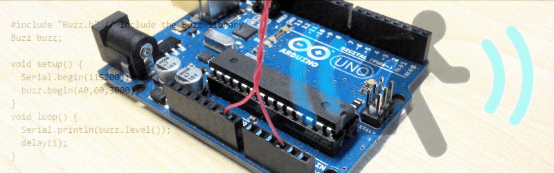
Either way, it was reliable enough a phenomenon that he put the promised time in and wrote a library. There’s even documentation on the GitHub. To initialize the library simply tell it which analog pin is hooked up, what the local AC frequency is (so its noise can be filtered out), and a final value that tells the Arduino how long to average values before reporting an event.
It seems to work well and might be fun to play with or wow the younger hackers in your life with your wizarding magics.


Hallo. It seems to react on static electricity. The graph is more active with the cat which is full charged. Try to wear clothes with nylon, move and the spikes will be higher.
I wonder if a variation on this method could detect wind, no not “Odeur du haricot” I mean air flow. If one pin has a signal on it and is connected to an antenna upstream of the detector wire the amplitude chance could be proportional to the air velocity. You’d need a routine to calibrate for humidity and other slow changing variables. Have two signals from antenna at right angles and the difference in the amplitude for the two frequencies may indicate relative humidity. That would be a nice hack, a 3 wire Arduino weather station, using the internal temperature sensor with a bit of calibration to get the correct reading.
I have seen arrangements with an upwind ion source and downwind detector.
I’m curious about the double antenna. Does it need 2 wires to work ? Can’t it work with only one ? And is it more efficient if they are closer ?
It’s a classic hacky way of making a very low value capacitor. There is some “free space” component to it’s charge storage.
I am fairly sure it all works by detecting change of capacitance with time as influenced by nearby conductive bodies. I’m fairly sure that if you swung a soft toy past it suspended on fishing line it wouldn’t twitch.
Oh, for want of a ‘like’ button.
It is know as a gimmick capacitor:
https://en.wikipedia.org/wiki/Gimmick_capacitor
Charged body moves closer, opposite charge accumulates in the wire, voltage is changed, nice.
I don’t think the body needs to be conductive, just charged.
Also not sure what the other wire is for — maybe providing a bit of extra capacitance to ground for the sense wire removes some noise?
Should be easy enough to test with something like a charged balloon on a pulley & string system
I have done this with code to make touch-style buttons out of nothing but a resistor and a flattened coil of wire. My method involves having a “charge” period, and then a “discharge” where I keep the pin high for a sufficient amount of time, then take the pin low and immediately measure the voltage on the line.
When a finger is close to the wire, it causes it to discharge a little slower, and therefore your ADC reading is higher within the LOW -> READ time period. Add some self-calibrating code to track and compensate for any drift and determine what a HIGH versus a LOW signal is, and you have a “touch” sensitive button. Actually think I made some ATTiny85 based boards that will “do” something with it’s free pins based off of this… like a programmable button of sorts.
https://en.wikipedia.org/wiki/Volt-ampere_reactive#Physical_significance_of_reactive_power
Look for that reactive electricity and copper winding (the twisted pair is one of this copper winding) and think about which kind of energy is present all the times inside your houses and rooms….think about the sensor in the reverse way ? the hat in Connors head could be a hint…… ^^^.
perhaps this guy is not wrong….
http://www.theunticket.com/wp-content/uploads/2010/11/conspiracy_theorist.jpg