If you enjoy building radio projects you may have noticed something slightly worrying over the last few years in your component supply. Variable capacitors are no longer as plentiful as they used to be. There was a time when all radio receivers contained at least one, now with the advent of the varicap diode and the frequency synthesiser the traditional tuning capacitor is a rare breed. They are still made, but they’re not cheap and they won’t appear so readily in your junk box any more.
Fortunately a variable capacitor is a surprisingly simple device, and one you can make yourself if you are of a mind to do so. [Patrick] did just that with his home-made capacitor, in this case of a few tens of pF and suitable as a low-power trimmer capacitor or in a single-chip FM radio.
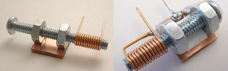
Rather than make a set of interlocking vanes as you’d find in a commercial design, he has gone for a screw in a tube. The capacitance is set by the length by which the screw is inserted into the tube. And his tube is not a tube in the traditional sense, instead he has used a coil of enamelled copper wire wound on the screw thread, whose insulation forms the dielectric. It looks wrong to use a coil in this way as you’d expect a similar coil to form the inductive part of a tuned circuit, but this coil is shorted out to prevent its inductance becoming a factor at the frequency in question.
It’s evidently not the answer to all variable capacitor problems, but it’s a neat piece of lateral thinking and it will make a simple working capacitor from readily available parts.
We’ve featured a couple of more traditional style home-made variable capacitors in the past on these pages, one made from thin aluminium sheet cut with scissors, and another one designed for use in higher power transmitters.
Thanks [PeterF] for the tip.


Wont it behave like a LC filter (similar to this: )
there was supposed to be an image there http://i.stack.imgur.com/GLwH7.png
Since the coil is shorted, the charge flows into each end of the coil more or less evenly, and a magnetic field is canceled before it can form. Any inductance is likely on the order of trace and component spacing.
Yes it’s just a coil for the sake of the threads in the bolt. There are other ways to get to the same end.
Michael
Nice find, thanks. I have been collecting documents on hand made electrical components and this idea is one even the kids can play with.
Try to get hold of these books? I Brought ‘The Voice Of The Crystal’ and ‘Instruments Of Amplification’ – both interesting reads about manufacturing radio components from scratch.
http://www.hpfriedrichs.com/mybooks/mybooks.htm
Thanks they look interesting, and “Artisan Ideas” have them in stock.
Trimmer, yes, tuner, don’t think that lacquer insulation will last long.
Agreed, perhaps some thread tape would solve that issue – maybe Teflon tape.
It *is* however a good way to get a reasonably consistent and repeatable result with standard wire gauges and thread sizes.
There were trimmers, maybe from Phillips, that amounted to a tube with screw that went down through it, each insulated from the other. So capacitance increased the deeper the screw was. These were trimmers for VHF, relatively small capacitance. But there was an article in QST about 1974, I think, about making “trombone” capacitors for HF use.
A slug tuned coil with the core replaced with metal, and some copper foil on the coil form might be simpler, though such coils may be as hard to get as trimmer caps. At some frequency it will change from a capacitor to a coil.
There were lots of schemes to make variables in the early days of radio, some were resurrected as project in the hobby magazines in the seventies.
I’m not sure I’d trust them for oscillator control, but once you figure out the mechanics, one could cut up plates of metal to make variables. I think I’ve seen some made with scrap circuit board. One company made low value trimmers with concentric cups, but I can’t think of an easy way to duplicate that.
Big transmitting loops need variable capacitors, some articles about those describe ways of making variable capacitors.
The real issue here is that for a few things, especially high power use, you need variable capacitors. But a lot of application has alternatives. Make the coils variable if you need trimming, instead of having trimmer capacitors in parallel. Varactors have taken over for many uses. But they won’t handle power.
Michael
Hmmm you could try something with cup washers and dielectric/insulation cut out of dollar store silicone bakeware. Some trimmers relying on compression to vary capacitance.
I used to work for a company that made variable air-gap trimmer capacitors. There were basically two different design styles: one which looked like the traditional many-interleaving-plates model you expect to see, and a tubular style. The tubular style had two pieces, each of which was made from a collection of small brass tubes with flanges on one end (maybe 1cm long, 4mm overall diameter) that were designed to nest. One piece was threaded, and they were mounted on a ceramic tube which allowed them to interleave concentrically.
You can think of it like your “tube with a screw in it”, and it worked similarly, but it had many concentric tubes, half of them mounted on a screw. Unfortunately, the product page from the company (that owned the company) I worked for doesn’t show how they work, only the finished capacitors. They look like ceramic tubes with electrical connections and gold end caps, not very enlightening.
Well, there’s also digitally tunable caps from Pericom that work super-nice. Move up into the new century!
Grr, Peregrine, not Pericom. A pair of PE64102s nets you basically the same range.
Would a helix in a helix also work? Take three tubes, two conductors and one insulator, or just insulate the two tubes. The tubes are sized to fit snugly inside the the larger tube. Fill the center with sand then wrap them around a bar to form a tight helix, then remove the bar and sand. Fix one conductor tube and you can slide the other one in and out by rotating it thereby controlling the area of the overlapping surfaces.
id be worried about the threads stripping the enamel.
A couple little details that come to mind:
1. The dielectric of a capacitor has a big effect on its Q and high frequency performance. I’d expect enamelled wire to be rather poor at VHF and higher frequencies.
2. The coil certainly *will* have inductance at VHF, even with its ends shorted. If you have a grid dip meter, it will show you the *other* resonances caused by these half-coils in series with your capacitance.
3. A metal slug inside a coil has the interesting property of *reducing* its inductance. There are slug-tuned coils where the slug is not ferrous (which increases inductance); but is instead is brass or copper, and *decreases* the inductance.
4. For home-built use, it is probably easier to use a fixed capacitor and make a tunable coil.
Wrap a glass test tube with metal foil or metal tape. Glue or otherwise fasten a nut to the open end of the tube, not touching the foil. screw a long bolt through the nut.
Wont the insulating enamel ware down pretty fast?
I have tried to make one. 22gauge enamel have I found to be ca. 0,65mm. The pcb 1/2″ or 12,7mm and the screw 16 mm as shownummer in drawing.. When I put it together the coil just enter, and it look not at al the shownummer result. WhatsApp do I do wrong, or is the screw to short.
It is not a variable capacitor , it’s a variable inductor. So we can use it instead of a inductor and can place a fixed value capacitor
My worry is that the enamel will eventually wear off the wire and short circuit to the screw. Or does the coil not touch the screw, IE: it’s ID is larger than the OD of the screw?