When we are taught about oscillators as newbie engineers, we are shown a variety of waveforms on an oscilloscope or in a textbook. This is a sine wave, they say, this is a sawtooth, this is a square wave, and so on. We’re taught to look at the lines on the screen as idealised, a square wave is truly square, and the transition from low to high voltage and back again is instantaneous.
In most cases this assumption is harmless. If we look into the subject a little deeper we learn that what seemed an instantaneous cliff-face is in fact a very steep slope, but when a circuit does its business in milliseconds there is usually no harm in ignoring a transition time measured in nanoseconds. The glue logic for your Arduino project can take its time.
Sometimes though, the rise time of a logic transition is important. The application that prompted this article was the measurement of oscilloscope bandwidth by looking at how quickly the ‘scope catches up with a pulse that exceeds its bandwidth, for example. When the instrument can happily measure the transition times of all your usual pulse generators, something out of the ordinary is called for. So it’s worth taking a look at the rise times you’d expect from everyday circuitry, examining a few techniques for generating rise times that are much faster.
That Was Considered Fast, Back In My Day
If you look at the data sheet for a typical transistor, you will find a section devoted to switching characteristics. Taking as an example the 2N3094 popular general purpose transistor, you’ll find it has a quoted maximum rise time of 35nS. Thus if you applied a perfect square transition to its base, the corresponding change at its collector would finish happening a maximum of 35 nS later. This might sound rather quick, but it corresponds to the rise time of a sine wave just over 7.14 MHz. Of course the 2N3904 is capable of working at much higher frequencies in small-signal mode, but if it has to traverse the entirety of its range you’re stuck at 7.14 MHz.
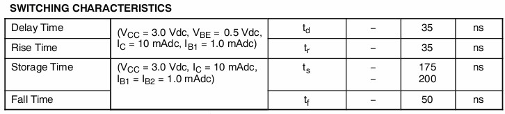
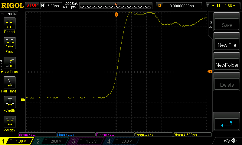
When it comes to faster transition times, you might expect our path to lead directly to components designed for square wave transitions, such as logic gates. But before we make that journey there is a surprising source of very fast rise times that’s not even electronic, it’s mechanical. The mercury-wetted relay is a type of reed relay in which the contacts are coated in mercury by capillary action. This produces an instantaneous contact, as the mechanism is that of liquid mercury droplets combining with each other rather than spring contacts touching. This contact time is well below a nanosecond, which means that the rest of the circuit around the relay and the voltage being switched governs the rise time, so extremely fast times can be achieved. We were fortunate enough to be able to borrow a mercury-wetted relay for this article, and when switching logic level into a 10 K resistor measured through an oscilloscope probe we were able to measure an impressive 4.6 nS rise time. This required some care with respect to lead lengths and ceramic decoupling capacitors to clean up and shorten the transition to this length, it is likely that further measures could shave some more time from this figure.
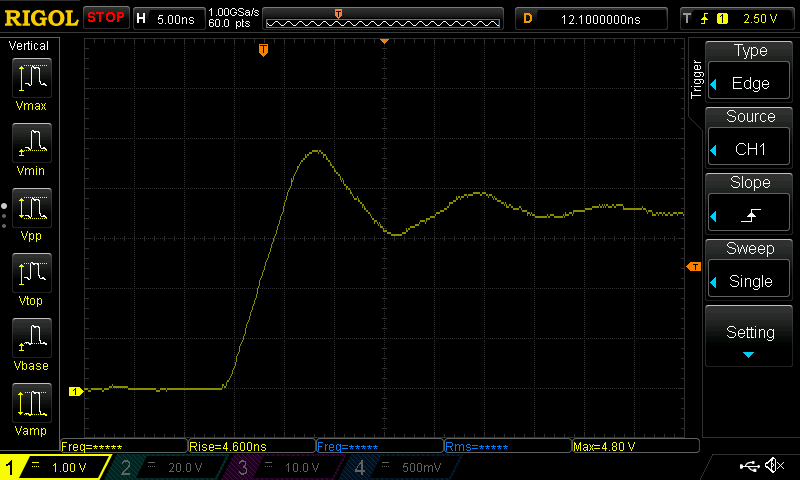
Logic gates are optimised for fast transitions, and should be correspondingly quicker than the 2N3904 we considered earlier. The archetypal logic gate family is of course the 74 series of TTL devices, of which there are many variants with ever-improving characteristics since the series first saw the light of day in the 1960s. We turned up the only original 74 series device we had to hand, a 7410 3-input NAND gate chip. Its data sheet quotes a typical low-to-high rise time of 11 nS, perhaps our device was one of the better ones as the ‘scope measured 7.1 nS. This corresponds to the rise time of a sine wave at about 35.2 MHz, but that figure is something of a theoretical upper maximum of the 7410’s performance envelope and the real usable figure would be rather less. Still, better than the 2N3904, but surely we can achieve more.
Casting around for higher speed 74 logic variants in a breadboard-friendly DIP package on the bench, the next up was a 74HC240 octal buffer. Around 20 years further up the technology ladder, and measured as having a rise time of 4.5 nS. Much better than the 7410, but still equal to the rise time of a sine wave at about 55 MHz.
More recent 74 series families offer improved rise times, but trawling through a lot of data sheets suggests that they still struggle to achieve significantly below 2 nS. As we move into the realm of picoseconds it’s obvious that we need something a little more special.
Speed Doesn’t Come Cheap… Or Does It?
Other devices optimised for very fast voltage transition aren’t hard to find, we’re used to using comparators to produce a quick logic level change based on the ratio of two analogue voltages. Of course, not all comparators are even in the class of the components above, the ubiquitous general-purpose LM139 and its derivatives for example have an almost leisurely 300 nS quoted transition time between TTL logic levels. But just as 74 logic has seen successive generations of technological improvement, so have comparators, and some of the more exotic devices leave the fastest 74 logic rise times in the dust. The ADCMP580 from Analog Devices for example is a SiGe emitter-coupled logic device that has a rise time of an astonishingly low 35 pS. There is a catch though: each chip will cost you around $18 and the evaluation board is just short of an eye-watering $300. That’s $8.30 per picosecond.
If you are seeking a picosecond-class rise time for the transition itself, as in our ‘scope bandwidth application, rather than for the timing while conveying some information, happily there is a much cheaper alternative. Avalanche breakdown is a phenomenon in which an insulator under an electric field can become conductive very rapidly indeed due to a chain reaction of accelerated free electrons dislodging more electrons. When applied to a transistor it can turn the device on much more rapidly than it would be when used in a conventional fashion, and it is this property that can be used to create a relaxation oscillator with an extremely fast pulse rise time. It is claimed a 2N3904 can achieve 500 pS rise times in this manner, something of an improvement on the 2N3904’s stock 35 nS mentioned above.
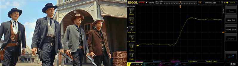
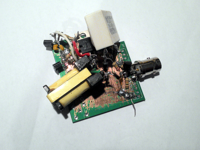
Of course, there is a catch with an avalanche pulse generator. The avalanche breakdown voltage of a bipolar transistor is quite hight, well over 100 V in the case of a 2N3904. Thus while the oscillator is simplicity itself, you are likely to need to also build some form of step-up power supply. If pushing boost converters beyond their usual boundaries is not yet your area of expertise, expect to plug that gap in your knowledge. It is, however, unusual to find a design that pushes the limits of what is possible in an area of electronics without resorting to exotic devices or special techniques, and as our rather messy prototype in the picture above shows this is a project that should be well within the abilities of many Hackaday readers. We’ll cover it in more detail in a future article as we examine its application, but meanwhile this piece would not be complete without a picture of it.
There is a satisfaction in achieving the fastest rise time, not dissimilar to that of achieving the most accurate frequency reference or atomic timepiece. We hope we’ve given you something of an introduction to some of the issues surrounding rise times in logic transition, and with the surprise that one of the fastest transitions can be achieved with components you are likely to have to hand then perhaps you’d like to have a go yourself.


If it’s $8.30 per picosecond, I’ll only take one.
:)
More seriously, if you only care about using the ADCMP580 as a fast edge, you can just dead-bug it and skip the eval board.
Pull the preamp off a discarded HDD. Drives >100 mA with <100 ps rise time. May be tough to find the datasheet however.
What era HDDs?
I’m about to condemn some older ones and part them out for motors and SRAM off the board, just curious as to what else I should look for and save.
All HDDs will have this device. Best specs will be on Enterprise 10k or 15k rpm HDDs post 2005 (once data rate plateaued out around 3 Gbps). Easiest to use would be on older HDDs. On modern HDDs the preamp module handles much more than just reading and writing (writing is where you get the fast rise times) and has lots of registers that need to be programmed over a serial interface.
FWIW the memory on the board will be DDR DRAM.
“FWIW the memory on the board will be DDR DRAM.”
Older
Oh and the static RAM is probably for the use of the microcontroller, buffers probably SDRAM and EDO and earlier DRAM depending on age.
The frame. If you ever want to mount something onto a really rigid structure, then the frame of an old 5.25 HDD is almost perfect.
That’s a point. Though even some 3.5s you could probably saw diagonal across the casting and it would make good rigid and fairly light brackets.
Do you mean this piece of mystery silicon on the RW head arm?
http://oi66.tinypic.com/2eaujv6.jpg
That’s the one
If you have not read IEEE std 1241 (Standards for Terminology and Test Methods for Analog-to-Digital Converters) I highly suggest borrowing from a library. It contains methods for making these difficult measurements.
I am surprised the authors here didn’t make any efforts to accurately measure their pulse widths. Trying to measure the output of a high performance relay using a 50MHz scope is like trying to measure the accuracy of your precision voltage reference with a harbor freight volt meter and then complaining that your reference is off by 10,000ppm. All that these results show (at least for the parts with sub-10ns switching times) is the errors in the test measurement.
P.S. – It was nice to meet your coworkers at Makerfaire.
The ‘scope in question is only 50MHz in software and marketing terms. I risk ruining the punchline of a forthcoming article by saying this, but the bit that matters in this context, the electrical bandwidth of its front end, is a very significant amount higher than that.
I’m really surprised that the easiest, cheapest way of making ~sub-ns edges isn’t mentioned: use a step-recovery diode. No step up required: just basically put a logic level through it, and the step-recovery portion of the diode sharpens one of the edges to a sub-ns edge.
A full example of generating a wideband pulse is here. The SRD there is a few bucks from Mouser.
So glad you mentioned this. Back in the day, we made pS rise times using SRD’s or tunnel diodes. This was used for exceedingly accurate triggering of things that made a huge a bang. Interesting times those.
I’m glad you mentioned this. Back in the day we created some crazy sharp rise-times, (10 pS or so as I recall?) using SRD’s and we did some fun things with tunnel diodes as well. This was all to achieve extremely high accuracy triggering on multiple channels to create a really big bang. Those were interesting times.
Like Bimini Atoll really big bang?
Bimini’s still there… Bikini, not so much.
Right, I was looking at boat awnings the other day, doh.
Gaas FETs? They’re designed for 5GHz+
I’ve got some RF amplifier chips in my parts drawer rated for 6GHz, probably the same thing.
There are other techniques for generating sub-ns (*not* sub-nS; S = Siemens = conductance) risetimes.
The early 70s Tektronix 485 scope’s <1ns risetime cal out signal is based on 2N6304 transistors, which aren't too different to 2N3904 (an fT of 1.2GHz rather than 300MHz).
An ~650ps 2.5V/50ohm risetime can be generated with moden jellybean logic. With good decoupling, having 3 sets of (74lvc1g14 + 130ohm) in parallel gives the "cable reference" waveforms shown in
https://entertaininghacks.wordpress.com/2016/09/17/scope-probe-accessory-higher-frequency-results/
That is also useful for checking the critical probe+ground probing techniques aren't disastrously modifying the displayed waveform.
And, of course, back in the early 1970s, 50ps risetimes were being generated using tunnel diodes.
That mistake of mine is irritating; my apologies. The correct URL for the 74lvc1g14 output is
https://entertaininghacks.wordpress.com/2015/08/11/measuring-digital-signal-edge-rates-without-an-oscilloscope/
The previous URL does, however, demonstrate the importance of probing techniques.
*Very* cool! Though it does require a spectrum analyzer ;-( Biasing to the transition region and then feeding random noise is slick.
Thanks.
That spectrum analyser is pretty cheap: it is an RTLSDR dongle!
See https://entertaininghacks.wordpress.com/category/frequency-domain-analysers/
for how to add other low-cost components to make a TDR and a scalar network analyser.
Please add a “continue reading” break
Reading from the comments, it seems the article was written by a very young engineer.
Why thank you! :)
nano-Siemens??? These rise times so fast they broke the units ! ! !
(don’t mean to troll… this is an awesome article Have to worry about triggering times quite a lot in a physics lab)
Boring!!
A 2N3904 can go faster. I am using one as an emitter follower for driving VGA video and getting to 10ns range. That is assuming your source has fast slew rate and enough drive current for the base. I have done a bit of tweak to compensation for the Miller capacitance etc, It is not just on LTSpice simulation either – see bottom of the page for actual scope picture.
https://hackaday.io/project/9992-low-cost-vga-terminal-module/log/33135-discrete-video-buffer
You do have to watch out for signal integrity as you push for faster slew rates as what you could get away with sloppy wirings e.g. non-terminated lines, mismatched impedances can come back to bite you. i.e. breadboards, dangling long pieces of loose wire, sloppy decoupling/power or ground connections etc. So be happy that your old 74 logic are slow and let you get away with a lot of things.
I am simply quoting the rail-to-rail figure from the datasheet. I routinely use them as very cheap class C RF PA stages in QRP VHF transmitters, in which they switch on and off a lot faster than the datasheet figure.
You may want to rebuild with a cleaner layout. I built something similar using ECL logic drivers spec’d at 1 ns and got nothing close to what I needed. After several iterations I concluded my primary problem was not maintaining constant 50 ohm impedance. If you’re trying to adjust the front end of a scope you don’t want a lot of ringing as it interferes with adjusting the overshoot. The problem really requires a stripline with SMD parts and very careful attention to connections.
I look forward to reading about your continuing adventures. I strongly recommend reading the “Digital Black Magic” books by Johnson & Graham. All of this is a wonderful way to learn about EM theory in a practical setting. Also very useful if you need to build a vector network analyzer fixture. If you’re going fast enough the roughness of the copper foil becomes an issue.
ECL is certainly better than totem-pole circuits, but if there is any imbalance in the complementary outputs then good decoupling rapidly becomes important.
Apart from that, I concur with your recommendation of Johnsons’ books – and website http://www.sigcon.com/
The messy layout is just the PSU and has no relevance to the pulse generator. That’s just the few components bunched on the back of the BNC socket. Any ringing in the traces is due to the very short BNC lead I was using.
Ideally it should be directly connected to a correctly terminated scope input. Even with a 350MHz scope and 650ps risetime, a run-of-the-mill 60cm 50ohm BNC cable affects the risetime.
And don’t forget that grounding and decoupling are very important.
Nice article, but a second is lower-case ‘s’. A siemens (electrical conductance) is a capital ‘S’.
1ns = a short time
1nS = 1GΩ
It makes people who use both units’ brains work harder.
Yes indeed. I have a multimeter (Fluke 25) with a nS scale, specifically for measuring resistors >32Mohm.
The lower and upper case are important for scientific units. Don’t arbitrarily use English language rules on scientific stuff they have their own rules.
I am puzzled by the fact that almost all logic gates have > 1 ns td’s. How do microprocessors manage to get to 4 GHz?
Low capacitance and electrically short transmission lines.
But there are other more serious problems: start by considering how far a signal can travel within one clock period at the speed of light (in Si), and compare that with the die’s size.
Not necessarily all problems. Back in the day we made custom integrated circuits for 10 GHz RADAR RF processing.
It turns out that if one can make the size of the circuits (at least) smaller than 1/4 wavelength then one is almost back to regular electronics again – no striplines or matched impedances and so on. “Integrated Life” becomes surprisingly simple compared to the discrete circuits we replaced.
Oh indeed :) 20 years ago I worked on a project at 60GHz. You know you aren’t in Kansas anymore when a simple 20dB antenna is the size of your thumb and it has an anti-reflection coating like you see on (optical) camera lenses. Back then it looked like the major system limitation would be thermodynamics: the transistor has to be small w.r.t. the wavelength, and the problem is getting the power away from that spot. AFAIK, not much has changed in that respect.
Well since high power and laser LEDs have that becoming more of a mass market problem now, cooling a tiny scrap of silicon, then maybe it will spinoff to progress in that.
Maybe, maybe not. Getting rid of heat from a semiconductor junction hasn’t changed much recently, especially in portable devices. (And it wasn’t silicon :) )
The logic gates themselves don’t have nanosecond propagation times. It’s the fact that you have to drive an off-chip trace with a huge voltage (relative to the minimum the transistors work at) and a huge capacitance (pF) that slows them down. Plus, those off-chip traces occasionally spike with kV of voltage, so you put this big freaking diode pair attached to them to stop it (ESD diodes), which also heavily slow the signal down.
That’s internal clock speed. Inside a chip, the distances are very small (compared with the rise/fall time) with very small capacitance to drive so there are things they can get away with and actually work at those kind of speed. For driving external signals, you have to go differential signaling with low signal swing. PCIe 2.0/3.0 (or similar) high speed links are what modern CPU use as front side bus to interface with the rest of the motherboard.
If you look at the right places, you can find small parts that handle GHz speeds. You may find SERDES, PHY, Receivers/Transmitter/MUX, but don’t expect to see your jelly bean 74xx-ish logics.
Sure you can, see the G series
ex http://www.potatosemi.com/potatosemiweb/datasheet/PO74G00A.pdf
I hope you have actually read the fine prints in that datasheet:
. Operating frequency up to 1.125GHz with 2pf load
. Operating frequency up to 750MHz with 5pf load
. Operating frequency up to 350MHz with 15pf load
This is the part that will kill all that performance:
Cin Input Capacitance (Vin = 0V) 4 pF
With real life parasitics on a PCB, I would seriously doubt that you won’t have a few pF of capacitance. Add to that 4pF *per* I/O, you won’t even get close to 750MHz.
If you are operating at those frequencies then either the PCB traces are electrically short and don’t add much capacitance, or they are transmission lines where the concept of capacitance is invalid.
In the latter case the driver only “sees” the transmission line impedance, and the 4pF input capacitance will affect the receiver, effectively forming a low-pass filter with 4pF driven by a resistor equivalent to the transmission line’s impedance.
And the real problem starts as soon as you want to hook up a scope to “see” how fast your rise time is. You just add another few picofarads of parasitic cap to the circuit and mess it all up. Guess the german saying we hear in our lab makes sense there: “Wer misst, misst Mist.” :)
Depends on the probe; with a low-impedance signal 0.7pF scope probe, the tip capacitance is not a dominant factor. (Example: HP10010A low impedance Z0 passive probe)
OTOH inductance in a ground connection can be very significant; see the URLs I posted earlier for examples. The TL;DR is 150mm ground lead (=>150nH) plus 15pF tip capacitance resonates at about 100MHz.
The tracks might be negligible (if the connection is less than a fraction of the rise/fall time), but don’t forget about the pads in the footprint for both sides (and vias if any). 0.8ns rise/fall time (from datasheet) means 1/2″ or less for track length. The parasitic capacitance of the pads can be significant. (pad to pad and pad to power/ground plane)
For a longer track, the transmission line etc will now add to the time delay for what the receiver sees. BTW The datasheet specifies the operation frequency is related to the propagation delay.
Don’t forget this is a single level of logic, so a realistic implementation of anything nontrivial would need more than that and more than a single fanout. So this series of logic is sub-GHz for all practical usage.
There’s no way you can make those measurements accurately enough with that scope/probe setup. The capacitive loading from your scope probe absolutely dominates the rise time of the circuits you’re looking for.
Jim Williams (one of the founders of LTI) did a lot of stuff on high-speed analog circuits. This early Linear app note shows how to properly measure some of these pulses, as well as practical nano-second circuits (better yet, made with breadboards in the 80’s – you can easily repeat this stuff).
This is probably in the top 3 of his most famous app notes. For high-speed analog, it’s the practitioner’s bible:
http://cds.linear.com/docs/en/application-note/an47fa.pdf
Similarly, this article talks about avalanche breakdown for very fast rise-times. There’s a practical through-hole transistor circuit from Jim Williams that gets sub-nanosecond (cites 520 ps) rise times:
http://www.edn.com/design/analog/4329164/Simple-nanosecond-width-pulse-generator-provides-high-performance
Modern versions of this circuit can get in the 100-200 ps range in the hobbyist range.
Is this one of those articles where Benchoff actually wrote it and put someone elses name on it to see if anyone would notice?
A cheap crappy Rigol scope…. for measuring fast rise times? WTF? That’s a joke right?
Just in case you want to talk to someone who actually knows what they are talking about, you should check this out….
http://www.siliconvalleygarage.com/projects/picosecond-pulser.html
No, it isn’t Brian’s.
If you take a look you’ll see that the rise times measured are all well within the capabilities of the Rigol, there’s no trace for the avalanche oscillator because it was specifically built to explore the Rigol’s limitations by being faster than it can handle.
The key sentence above that many commenters seem to have missed is this: “The application that prompted this article was the measurement of oscilloscope bandwidth by looking at how quickly the ‘scope catches up with a pulse that exceeds its bandwidth”.
If I made the short trip down the road to Harwell and called in a few favours I am sure I could find both pulse rise times at the limit of science and the instruments to measure them. This article is not however about that, instead it’s about how to create a quick rise time for the instruments on your bench.
If you are operating at those frequencies then either the PCB traces are electrically short and don’t add much capacitance, or they are transmission lines where the concept of capacitance is invalid.
In the latter case the driver only “sees” the transmission line impedance, and the 4pF input capacitance will affect the receiver, effectively forming a low-pass filter with 4pF driven by a resistor equivalent to the transmission line’s impedance.
Please ignore that duplicate post; the reason for the duplication is too boring to explain and would invoke any sane person’s TL;DR filter.
Little correction on your text there: “Taking as an example the 2N3094 popular general purpose transistor, you’ll find it has a quoted maximum rise time of 35nS. Thus if you applied a perfect square transition to its base, the corresponding change at its collector would finish happening a maximum of 35 nS later.”
Did you even see the line inthe datasheet just above that says “Delay”? It’s rated at 35ns too, so you would expect the change at the collector to happen a maximum of 70ns (delay+rise-time) after you’ve applied the impulse on the input.
In my past, I worked on Ultra Wideband Radar- The first pulser we used was a “Bulk Avalanche Semiconductor Switch” – The company was Power Spectra, which was bought by Boeing. This used a planar triode to generate a fast pulse, but that was only to charge up a little bit of stripline- once the line was charged, we hit the avalanching device with a laser pulse, which precipitated the avalanche. We got rise-times in the Picoseconds- but the truly amazing thing- our peak voltage was in the kilovolts into a 50 ohm load. Later we got a pulser that would do 10KV into 50 ohms by avalanching a stack of transistors- I think we had a 90ps rise time 10KV pulse, with an extended fall (maybe 2ns)- all into 50 Ohms.