How Much Bandwidth Does CW Really Occupy?

Amateur radio license exams typically have a question about the bandwidths taken up by various modulation types. The concept behind the question is pretty obvious — as guardians of the spectrum, operators really should know how much space each emission type occupies. As a result, the budding ham is left knowing that continuous wave (CW) signals take up a mere 150 Hertz of precious bandwidth.

But is that really the case? And what does the bandwidth of a CW signal even mean, anyway? To understand that, we turn to [Alan (W2AEW)] and his in-depth look at CW bandwidth. But first, one needs to see that CW signals are a bit special. To send Morse code, the transmitter is not generating a tone for the dits and dahs and modulating a carrier wave, rather, the “naked” carrier is just being turned on and off by the operator using the transmitter’s keyer. The audio tone you hear results from mixing the carrier wave with the output of a separate oscillator in the receiver to create a beat frequency in the audio range.

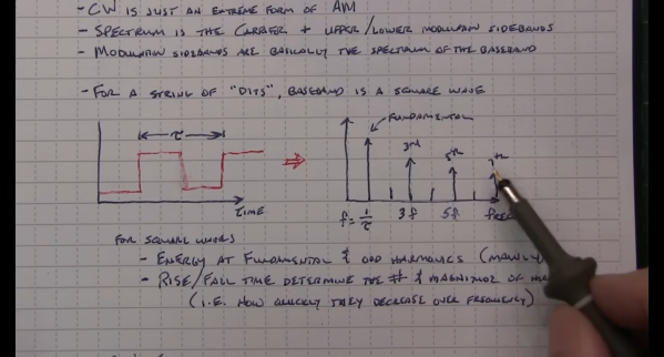
That seems to suggest that CW signals occupy zero bandwidth since no information is modulated onto the carrier. But as [Alan] explains, the action of keying the transmitter imposes a low-frequency square wave on the carrier, so the occupied bandwidth of the signal depends on how fast the operator is sending, as well as the RF rise and fall time. His demonstration starts with a signal generator modulating a 14 MHz RF signal with a simple square wave at a 50% duty cycle. By controlling the keying frequency, he mimics different code speeds from 15 to 40 words per minute, and his fancy scope measures the occupied bandwidth at each speed. He’s also able to change the rise and fall time of the square wave, which turns out to have a huge effect on bandwidth; the faster the rise-fall, the larger the bandwidth.

It’s a surprising result given the stock “150 Hertz” answer on the license exam; in fact, none of the scenarios [Allen] tested came close to that canonical figure. It’s another great example of the subtle but important details of radio that [Alan] specializes in explaining.

Continue reading “How Much Bandwidth Does CW Really Occupy?”

The Dipole Antenna Isn’t As Simple As It Appears

Dipole antennas are easy, right? Just follow the formula, cut two pieces of wire, attach your feedline, and you’re on the air.  But then again, maybe not. You’re always advised to cut the legs a little long so you can trim to the right length, but why? Shouldn’t the math just be right? And what difference does wire choice make on the antenna’s characteristics? The simple dipole isn’t really that simple at all.

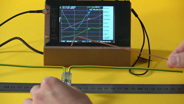
If you’ve got antenna questions, check out [FesZ]’s new video on resonant dipoles, which is a deep dive into some of the mysteries of the humble dipole. In true [FesZ] fashion, he starts with simulations of various dipole configurations ranging from the ideal case — a lossless conductor in free space with as close to zero diameter conductors as the MMANA antenna simulator can support — and gradually build up to more practical designs. Continue reading “The Dipole Antenna Isn’t As Simple As It Appears”

Bufferbloat, The Internet, And How To Fix It

There’s a dreaded disease that’s plagued Internet Service Providers for years. OK, there’s probably several diseases, but today we’re talking about bufferbloat. What it is, how to test for it, and finally what you can do about it. Oh, and a huge shout-out to all the folks working on this problem. Many programmers and engineers, like Vint Cerf, Dave Taht, Jim Gettys, and many more have cracked this nut for our collective benefit.

When your computer sends a TCP/IP packet to another host on the Internet, that packet routes through your computer, through the network card, through a switch, through your router, through an ISP modem, through a couple ISP routers, and then finally through some very large routers on its way to the datacenter. Or maybe through that convoluted chain of devices in reverse, to arrive at another desktop. It’s amazing that the whole thing works at all, really. Each of those hops represents another place for things to go wrong. And if something really goes wrong, you know it right away. Pages suddenly won’t load. Your VoIP calls get cut off, or have drop-outs. It’s pretty easy to spot a broken connection, even if finding and fixing it isn’t so trivial.

That’s an obvious problem. What if you have a non-obvious problem? Sites load, but just a little slower than it seems like they used to. You know how to use a command line, so you try a ping test. Huh, 15.0 ms off to Google.com. Let it run for a hundred packets, and essentially no packet loss. But something’s just not right. When someone else is streaming a movie, or a machine is pushing a backup up to a remote server, it all falls apart. That’s bufferbloat, and it’s actually really easy to do a simple test to detect it. Run a speed test, and run a ping test while your connection is being saturated. If your latency under load goes through the roof, you likely have bufferbloat. There are even a few of the big speed test sites that now offer bufferbloat tests. But first, some history. Continue reading “Bufferbloat, The Internet, And How To Fix It”

From Nanoamps To Gigahertz: The World’s Most Extreme Op Amps

The operational amplifier, or op amp, is one of the most basic building blocks used in analog circuits. Ever since single-chip op amps were introduced in the 1960s, thousands of different types have been developed, some more successful than others. Ask an experienced analog designer to name a few op amps, and they’ll likely mention the LM324, the TL072, the NE5534, the LM358, and of course the granddaddy of all, the uA741.

If those part numbers don’t mean anything to you, all you need to know is that these are generic components that you can buy anywhere and that will do just fine in the most common applications. You can buy fancier op amps that improve on some spec or another, sometimes by orders of magnitude. But how far can you really push the concept of an operational amplifier? Today we’ll show you some op amps that go way beyond these typical “jellybean” components.

Before we start, let’s define what exactly we mean when we say “operational amplifier”. We’re looking for integrated op amps, meaning a single physical component, that have a differential high-impedance voltage input, a single-ended voltage output, DC coupling, and high gain meant to be used in a feedback configuration. We’re excluding anything made from discrete components, as well as less-general circuits like fixed-gain amplifiers and operational transconductance amplifiers (OTAs).

Continue reading “From Nanoamps To Gigahertz: The World’s Most Extreme Op Amps”

Say It With Me: Bandwidth

Bandwidth is one of those technical terms that has been overloaded in popular speech: as an example, an editor might ask if you have the bandwidth to write a Hackaday piece about bandwidth. Besides this colloquial usage, there are several very specific meanings in an engineering context. We might speak about the bandwidth of a signal like the human voice, or of a system like a filter or an oscilloscope — or, we might consider the bandwidth of our internet connection. But, while the latter example might seem fundamentally different from the others, there’s actually a very deep and interesting connection that we’ll uncover before we’re done.

Let’s have a look at what we mean by the term bandwidth in various contexts.

Continue reading “Say It With Me: Bandwidth”

X-Rays Are The Next Frontier In Space Communications

Hundreds of years from now, the story of humanity’s inevitable spread across the solar system will be a collection of engineering problems solved, some probably in heroic fashion. We’ve already tackled a lot of these problems in our first furtive steps into the wider galaxy. Our engineering solutions have taken humans to the Moon and back, but that’s as far as we’ve been able to send our fragile and precious selves.

While we figure out how to solve the problems keeping us trapped in the Earth-Moon system, we’ve sent fleets of robotic emissaries to do our exploration by proxy, to make the observations we need to frame the next set of engineering problems to be solved. But as we reach further out into the solar system and beyond, our exploration capabilities are increasingly suffering from communications bottlenecks that restrict how much data we can ship back to Earth.

We need to find a way to send vast amounts of data back as quickly as possible using as few resources as possible on both ends of the communications link. Doing so may mean turning away from traditional radio communications and going way, way up the dial and developing practical means for communicating with X-rays.

Continue reading “X-Rays Are The Next Frontier In Space Communications”

Video: Putting High Speed PCB Design To The Test

Designing circuit boards for high speed applications requires special considerations. This you already know, but what exactly do you need to do differently from common board layout? Building on where I left off discussing impedance in 2 layer Printed Circuit Board (PCB) designs, I wanted to start talking about high speed design techniques as they relate to PCBs.  This is the world of multi-layer PCBs and where the impedance of both the Power Delivery Network (PDN) and the integrity of the signals themselves (Signal Integrity or SI) become very important factors.

I put together a few board designs to test out different situations that affect high speed signals. You’ve likely heard of vias and traces laid out at right angles having an impact. But have you considered how the glass fabric weave in the board itself impacts a design? In this video I grabbed some of my fanciest test equipment and put these design assumptions to the test. Have a look and then join me after the break for more details on what went into this!

Continue reading “Video: Putting High Speed PCB Design To The Test”