Every now and then you need to make your own capacitor. That includes choosing a dielectric for it, the insulating material that goes between the plates. One dielectric material that I use a lot is paraffin wax which can be found in art stores and is normally used for making candles. Another is resin, the easiest to find being automotive resin used for automotive body repairs.
The problem is that you sometimes need to do the calculations for the capacitor dimensions ahead of time, rather than just throwing something together. And that means you need to know the dielectric constant of the dielectric material. That’s something that the manufacturer of the paraffin wax that makes it for art stores won’t know, nor will the manufacturers of automotive body repair resin. The intended customers just don’t care.
It’s therefore left up to you to measure the dielectric constant yourself, and here I’ll talk about the method I use for doing that.
What is Dielectric Constant?
If you’re wondering what a dielectric constant is, don’t worry because you’re not the only one. Let’s start with a short explanation.
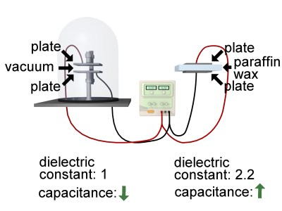
Let’s say you have a flat plate capacitor with nothing between the plates, literally a vacuum. That capacitor will have a specific capacitance, which is a measure of its ability to store charge on the plates. If you instead insert an insulating material in between the plates, wax for example, then that capacitor will have a higher capacitance, a greater ability to store charge on the plates. Putting an insulating material between the plates increases the capacitance.
The dielectric constant is the measure of how much that capacitance increased when you insert that material. It’s the ratio of the capacitor’s capacitance with the material, to its capacitance with a vacuum instead. For example, if you search online you’ll find that paraffin wax has a dielectric constant of somewhere between 2.1 to 2.5. Below you’ll read how I measured mine as 2.2.
Physicists have long ago defined the dielectric constant of a vacuum to be 1. That means that paraffin wax in a capacitor gives the capacitor 2.2 times the ability to store charge as if there was just a vacuum there instead (2.2 times as much as 1, is 2.2).
Terminology
Before we go further, let me point out that the term dielectric constant is actually deprecated and physicists and engineers use relative permittivity instead. But its usage is still widespread and most tables you’ll find online use the heading, dielectric constant.
You’ll also often see the dielectric constant represented in formulas as Κ (the Greek letter kappa) or εr (the Greek letter epsilon and an r for relative).
Measuring The Dielectric Constant
We should first start with a caveat. The dielectric constant varies according to temperature. It decreases with increasing temperature. For most materials the variance is small. Whenever I’ve measured a dielectric constant, it’s always been for use at room temperature and 0Hz.
Knowing that the dielectric constant is the ratio of the capacitor’s capacitance with the material to its capacitance with vacuum gives you a way to measure it. As I said, the dielectric constant of vacuum is 1, but the dielectric constant of air is 1.0005, which is pretty much the same. So if Cm is the capacitance of the capacitor with your material and Ca is the capacitance with air instead, then the dielectric constant is Cm/Ca i.e. the ratio of the two.
That means that to get the dielectric constant, simply measure the capacitor’s capacitance with the material in place (Cm), and then measure its capacitance again but without the material i.e. with air instead (Ca). Divide the first value (Cm) by the second value (Ca) and you’ve got the material’s dielectric constant.
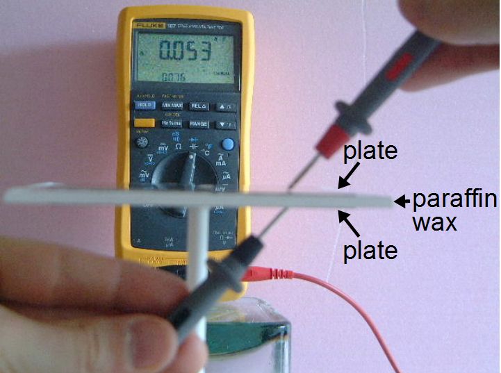
In the photos below I’m determining the dielectric constant for paraffin wax I bought at a local art store.


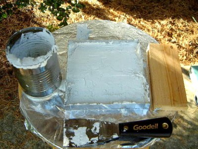
I first measure the capacitance of the wax capacitor, shown in the first two photos. I made a 4mm thick, square piece of wax. For the plates I cut some square pieces of aluminum flashing which, when placed on the wax, don’t quite cover all of the wax surface.
I hot glued one plate to the top of a plastic tube to suspend it in the air. I then build a capacitor sandwich by placing wax on the first place, then the other plate on top of the wax. As you usually do when measuring capacitance, before making the measurement I use the meter’s REL function to store the capacitance of just the probes themselves. That zeros out the meter. Then I measure the capacitance of the plates and wax capacitor. I get 0.053nF, which is my Cm.


Next up is to measure the capacitance of the air capacitor, shown in the two photos above. I hot glue the other plate to another plastic tube and arrange the plates 4mm apart with only air between them, making sure the spacing is the same as when the wax was between the plates. That creates the same capacitor with the only difference being the use of air as the dielectric. I get a capacitance of 0.024nF, which is my Ca.
Doing the calculation, the capacitance with the wax (Cm), 0.053nF, divided by the capacitance with air (Ca), 0.024nF, I get a dielectric constant of 2.2. Note that it’s dimensionless since it’s a ratio of two values that have the same dimensions. Searching online, most tables give a range for paraffin wax of 2.1 to 2.5 so I’m pretty confident of my result.


In this set of photos I’m using the same procedure to measure the dielectric constant of a mix of barium titanate and epoxy resin, made for a cylindrical capacitor as I describe in my article Homemade Capacitors of a Mad Scientist. The inner plate is a 1/4″ diameter copper rod and the outer plate for the purposes of determining the dielectric constant is an aluminum cylinder which you can see wrapped around the barium titanate and resin dielectric cylinder. The copper rod was much longer than it needed to be so to measure the capacitance in air I simply moved the aluminum cylinder to a length of the rod where there is no dielectric.
The capacitance with the barium titanate and epoxy resin mix is 0.075nF (Cm) and the capacitance with air is 0.005nF. 0.075nF divided by 0.005nF gives a dielectric constant of 15. In the article linked to above I talk about a value of 27, but I don’t have photos of making the measurements for that version.
Other Considerations
Two other considerations for your own measurements are resistivity and the effect of the edges.
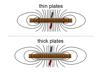
If you have a flat plate capacitor then you can envision the electric field as shown by the lines in the diagram. Notice that the electric field is different at the edges than it is between the plates. Notice also that it’s different depending on the geometry of the plates. Thin plates have sharper edges, for example, and will have denser electric field lines at the edges. But we’re interested only in what happens to the material in the area between the plates, not at the edges. One way to minimize the effect of the edges on our measurements is to simply have a large plate area compared to the amount of edge, making the edge less significant.
The other thing to consider is the resistivity of your dielectric material. Naturally you’ll want your capacitor to have a good insulator as the dielectric. But since we’re doing homemade stuff here, it’s possible that you’ve made a dielectric material that has some conductivity. So after you’ve made your dielectric material, put some plates on either side and measure the resistance from plate-to-plate using the resistance scale of your meter. It should show whatever your meter normally shows for something that has too high a resistance to measure.
I ran across this resistivity problem once. A friend and I made a barium titanate and wax capacitor and for some reason the resistance when assembled as a capacitor was 2.31 Mohms. We guessed that maybe the air was humid outside when the barium titanate and hot wax mixture cooled, and some moisture got into the mix. So we put it in the oven at 110C (230F) for 65 minutes to remove the moisture. After it cooled we measured the resistance again. It was greater than 20 Mohms, higher than the meter could measure.
Conclusion
And that’s how I measure the dielectric constant, or relative permittivity, of a dielectric material. If you’ve measured the dielectric constant of a material, I’d be very interested in knowing how you went about it, along with any special considerations. Let us know in the comments below.


What happens if your paraffin solidified in a strong electric field? Ideally no difference, but it depends on how the capacitance meter works. Maybe a metal mold so there is no field inside.
You would have an electret
https://en.wikipedia.org/wiki/Electret.
When experimenting with dielectric constant, try water.
You can make a really nice capacitive level sensor out of a pice of Twin-lead.
https://en.wikipedia.org/wiki/Twin-lead
This is very useful, thanks!
You can look up tables like this, https://www.kabusa.com/Dilectric-Constants.pdf but as you will see for some substances, paraffin wax being a good example, it will have a range of values therefore you still need to be able to measure the value for the specific product you have on hand.
Handy for making EL displays, I’d like to try this sometime with the phosphor powder.
wax+BaTiO3
Some of what you have written is not correct. The permittivity (dielectric constant ) of a vacuum is not 1, it is approximately 8.85pf/m. The lower case r paired with the epsilon means relative, as you said. So, the relative permittivity of a vacuum is 1. You also said that you measure the permittivity of your DIY capacitors at 0 Hz. I am sure if you check the manual for your meter you will find that it uses a low frequency to measure capacitance. While you mention that the permittivity of a dielectric depends on temperature. It also depends on frequency. Some dielectrics vary quite a bit with frequency, and others have a relatively flat dielectric constant. If you plan to use your DIY capacitors at a different frequency than your meter uses to measure capacitance you may be disappointed with the results.
but why the vacuum is not 1, it is approximately 8.85pf/m? how this number is derived?