“The great thing about standards is that there are so many to choose from.” Truer words were never spoken, and this goes double for the hobbyist world of hardware hacking. It seems that every module, every company, and every individual hacker has a favorite way of putting the same pins in a row.
We have an entire drawer full of adapters that just go from one pinout to another, or one programmer to many different target boards. We’ll be the first to admit that it’s often our own darn fault — we decided to swap the reset and ground lines because it was convenient for one design, and now we have two adapters. But imagine a world where there was only a handful of distinct pinouts — that drawer would be only half full and many projects would simply snap together. “You may say I’m a dreamer…”
This article is about connectors and standards. We’ll try not to whine and complain, although we will editorialize. We’re going to work through some of the design tradeoffs and requirements, and maybe you’ll even find that there’s already a standard pinout that’s “close enough” for your next project. And if you’ve got a frequently used pinout or use case that we’ve missed, we encourage you to share the connector pinouts in the comments, along with its pros and cons. Let’s see if we can’t make sense of this mess.
FTDI TTL Serial
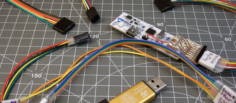
The de-facto standard for a hacker’s TTL serial pinout is definitely the layout that FTDI uses for their USB/TTL serial cables. Said cable is just so handy to have on hand that you’d be silly to use any other pinout for the job. And the good news is that the rest of the world has basically joined in. From the Chinese “Pro Mini” cloneduinos to the Hackaday Edition Huzzah ESP8266 board, and from Adafruit’s FTDI Friend to Modern Device’s USB-BUB, almost everyone uses this pinout. A victory for the common man!
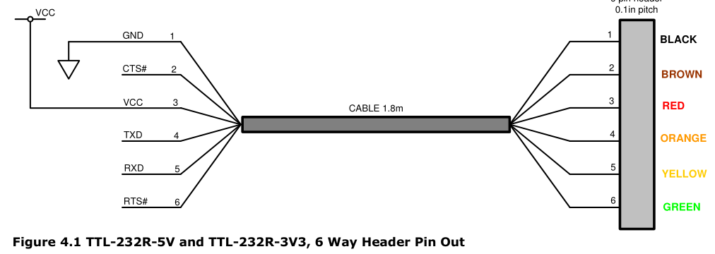
There is one slight point of contention, however, and that’s whether pin 6 is DTR or RTS#. We never use either, so we couldn’t care less, but if you’re counting on your programmer sending the DTR signal to enter programming mode on the device (we’re looking at you Arduino!) then you’ll want DTR on pin 6, and the original FTDI cable, ironically, has the “wrong” pinout. Perhaps that’s why Sparkfun avoided the whole debacle and went their own way, breaking out every signal off the FTDI chip into their own unique configuration.
If you’re only going to break out TTL serial lines, you’d be a fool to use any other pinout.
Modules and Other Communications
Unlike the case with simple serial, connecting various kinds of modules to mainboards is a difficult problem. Creating a single pinout or connector specification for many potential protocols or arbitrary signals is a Herculean task. Surprisingly, it’s been done a few times over. Here are some notables.
Pmod
Digilent makes a wide range of FPGA demo boards, and they needed an in-house standard pinout that they could use to plug into various add-on peripheral modules that they sell. Thus Pmod was born. It has since become a full-fledged, and trademarked, open standard that you can use in your designs. Here’s the PDF version of the specification for you to print out, so you know they mean business.
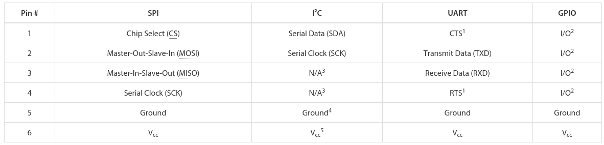
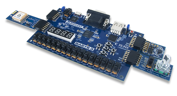 There are a few aspects of Pmod that we think are particularly clever. First, the number of pins involved is “just right” at six, and it’s easily expandable. They use standard 0.1″ pitch pins and headers. Two lines carry power and ground, leaving four free pins for SPI, UART, or whatever else. The specification is that all power and signal voltages are 3.3 V because they’re designed for FPGAs after all. You can mix and match if you know what you’re doing, but they won’t let you call it Pmod(tm).
If you need more than four signals, there’s a twelve-pin version which is just two six-pin Pmods stacked into a double-row header. The extra power and ground are redundant, but it makes a twelve-pin output very flexible, because nothing stops it from being used as two sixes. The standard also says that the twelve-pin headers are to be spaced at 0.9″ center-to-center, so you can even connect two of them together when you need sixteen board-to-board signal connections. We like the modularity and expandability.
Pmod connectors are multi-protocol, but for each protocol there is a single pinout. So there’s an SPI Pmod and an I2C Pmod, and the pins are always in the same place. There isn’t a Pmod standard for every conceivable application, of course, so there’s a GPIO pinout that gives you free rein over what goes where. We think that it would be nice if some additional notable protocols (I2S? one-wire? servos? analog stereo audio?) were included in the specs, but the community can also handle these lower-level details.
 In our eyes, Pmod is nearly perfect. It uses cheap hardware, is easily expandable, and the smallest incarnations are small enough to fit on all four sides of a one-inch-square board. If you’re willing to pay the brand-name premium, Digilent makes an incredible range of modules. We want to see more hackers outside of the FPGA scene get on it.
mikroBUS
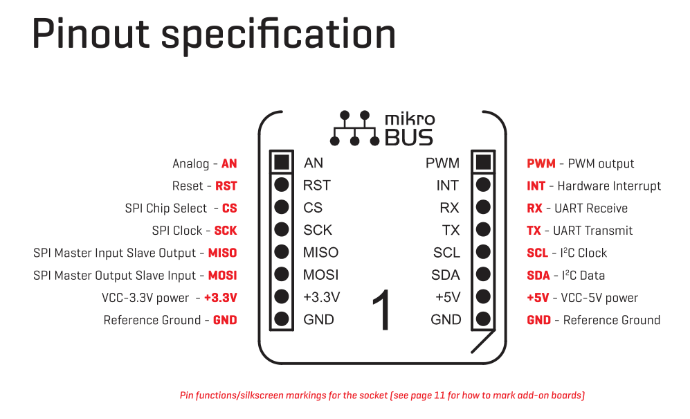 What Digilent is to development boards in the US, MikroElektronika is in Europe. While Pmod aims to be capable of doing anything, Mikro-E’s mikroBUS connector wants to do everything, which is to say it has I2C, SPI, UART, two voltages, and even a few extra signals all on the same pinout. Physically, it’s two single rows of eight pins, spaced 0.9″ apart side-to-side, which means it fits into a breadboard nicely. Here’s the spec in PDF.
The tradeoff here, relative to Pmod, is that a lot of pins go unused on any given design. With (only) one “analog” channel, you wouldn’t choose mikroBUS to send stereo audio, whereas nothing stops you from calling the Pmod’s GPIO lines analog and sending four channels of sound. But that mikroBUS gains is fool-proofness. (Well, they could have also made it asymmetric…) There’s no chance of a newbie plugging an SPI module in where an I2C module is expected and scratching their heads. With mikroBus, it should just work.
Microchip has added a mikroBus port to their Curiosity boards, and MikroElektronika makes a ton of modules. If your audience consists of beginners, and one footprint for all protocols, it’s worth considering.
Seeed’s Grove
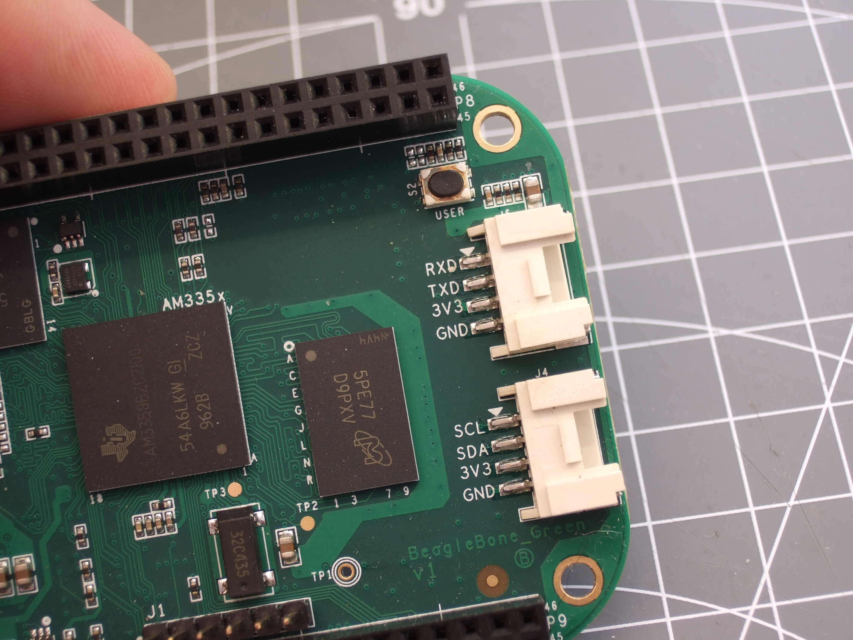 Meanwhile in China, Seeed Studios makes open-source modules, and makes them cheap. Their Grove connector uses only four pins, with power and ground among them. The have standard pinouts for UART, I2C, and for servo motors. Sensors and other analog peripherals are allocated one “primary” pin and one “secondary” and it’s assumed that you know what you’re doing. The idea behind their system is that you add a shield to your microcontroller board, and they break out the relevant pins into these four-pin Grove headers.
This is great for small things and I2C devices, which is Seeed’s catalog, but there just aren’t enough signal pins to run SPI or an analog RGB LED, for instance. But because of the small number of pins, they use very inexpensive polarized cables and shrouds that you can’t plug in the wrong way, and that take up relatively little board space. That’s Grove’s design trade-off.
Servo Motor control
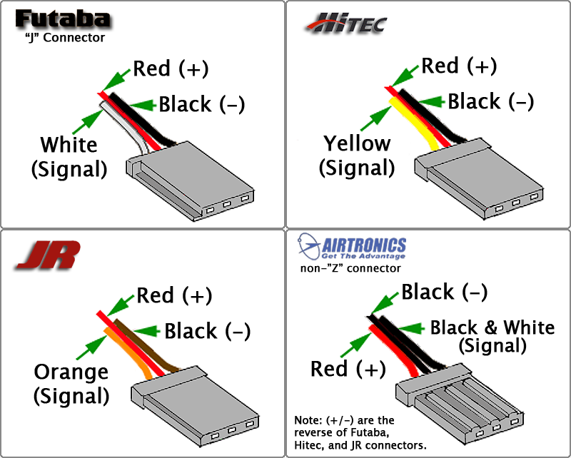
Hobby servo motors need three wires: voltage, ground, and a signal to tell them where to point. There are three distinct ways to arrange these wires, but Futaba, HiTec, Tower, GWS, and JR servos all chose to put them in SVG (or GVS) order, and there’s no reason to buck the trend. (Airtronics, what were you thinking?!)
SVG is also a handy pinout to use for all sorts of one-signal sensors or actuators where space is a premium, and we’ve seen this in a few designs (here and here, for instance). But we’re torn. Relative to the Grove, for instance, you’re just saving one pin. Even the Pmod would work with only three pins’ overhead. Is that worth complicating your life with another pinout? If you need a lot of powered one-signal devices, or servos, it probably is, and you can hardly beat SVG or GVS, whichever way you look at it.
Arduino
Viewed in the light of any of the other module interconnection systems, the Arduino is the worst of all worlds. It’s monolithic like mikroBUS, but it’s gigantic — you have to build a 55×73 mm board and accommodate 30 pins and pass-throughs if you’d like it to be stackable. The pins have a funny spacing (that gap!), that doesn’t fit any normal protoboard. Nobody goes through the trouble of building a shield just for an I2C connection. No wonder most Arduino projects look like a breadboard hedgehog. About the only good thing we can say about it is that it’s hard to plug one in backwards.
There’s also the tiny little factor that there’s a million Arduino shields out there, a huge community built around them, and widespread support for them. Which turns out to trump all of the reasonable design concerns. (Shakes head.)
Miscellany
 Of course, there are other very specific pinouts that one might encounter, like the old ESP-01 module, or the XBee, or the nRF24. Adapting modules to fit boards is always going to be a pain, because the manufacturers will pick whatever suits them on that day. Programmer pinouts for specific microcontrollers are a similar story, as is JTAG, which is a beautiful standard with a dogs’ breakfast of pinout possibilities. (We could do a whole column!)
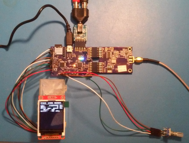
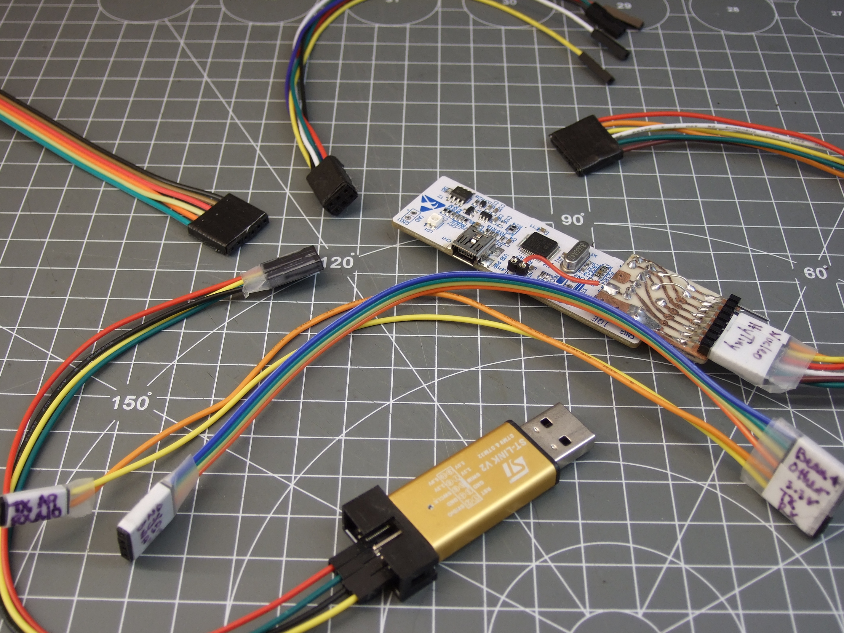
Faced with this inevitability, and the need for many one-off adapters, what can you do? What we do is buy a lot of those cheap “Dupont” female-to-female cables, get the connections working and tested, and then tape them permanently together and label them. It’s not as pretty as a dedicated PCB adapter, but it’s quick and easy and gets you moving on to what you wanted to do in the first place.
Wrapup and Recommendations
The goal of connectors, and their standards, is putting parts together. If you’re designing a sensor module with more than a couple components, and you want it to be maximally easy for yourself and others to hook up to whatever mainboard they’ve got, this is no easy task. The end result is a proliferation of translators, adapter boards, hats, shields, capes, or whatever else. We have a drawer and a half full, and we bet you do too.
What’s your solution to the ultimate connector conundrum? Are there important connector systems that we’ve left out? What are their design tradeoffs? How stoked would you be if things could just plug together? Let us know!
Thumbnail image courtesy of [Raspberry Pi Controller].


I’m for PMOD as well, if a connector cannot support an SPI, then it’s no good in most cases.
You posted the xkcd before the HaD readers got a chance. Not cool, [Elliot Williams]. :P
Interesting article; I’m always lost when it comes to connecters, gotta label everything besides power.
There is always one more. This articles about connectors/adapters after all…
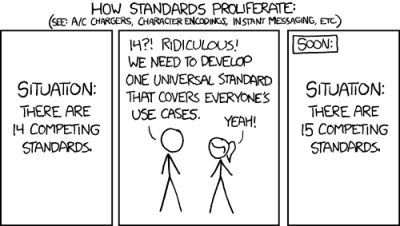
https://xkcd.com/1406/
Touché!
“There’s always one more XKCD” should be an XKCD…
If you only care about 2 of the pins, you’d be a fool to use any pinout that assigns some other potentially useful thing to those pins?
I find that such a strange claim, because I use a different brandybrand and instead of hardware flow control it gives me both +3V and +5V supplies, which is way more useful than some wires that I don’t care about, but wanted to be thing one thing I’m not using.
Yeah, actually first time I heard anyone using the FTDI cable pinout. The FTDI cables I have used have been with separate connector for each wire. On my own boards, I usually just use 3 pins GND/RX/TX.
that’s exactly what I thought when I read this… huh… is there a standard? What about all those USB to TTL serial cables then… you know those cables with the lose wires that you must connect to the proper pin on your breadboard.
So, I guess we can say that today I’ve learned something.
Thank you Hackaday.
The FTDI pinout seems a bit poorly thought out. Most embedded stuff uses pwr/gnd/rx/tx , few things use the hardware flow control pins these days, so why not put the important ones together? The target board can then just have a 4-pin header and let the rest dangle.
I never had this problem. I just use jumper wires to connect everything the way I like. This way I don’t need to make any custom adapter cables. One doesn’t need to adopt any standard as long as he can connect appropriate IO pins together. However anything proprietary, including Arduino, is evil and thus should be destroyed by any means necessary…
I like this idea. If only everyone would add a label directly in copper or the silkscreen at the pins so you can quickly identify the signal…
I’ve recently been trying to decide on a standard pin out for my programming port, I have used the Tag Connect connector for a while, but it’s a bag of crap.
I’ve finally settled on a 10pin 0.05inch pitch pin header connected via idc cable to a breakout board. Down this I can get programming signals, I2c and UART from the processor. After having to try and solder wires to vias too many times to analyse these, I figured it’s best to always break them out.
Bit harder to get 0.05inch as opposed to 0.1inch but the space saving is massive.
Currently working on a FPGA version to have both JTAG and 4 FPGA I/O lines, and an ARM version. Just laying out all three pathways onto a single pcb at the moment.
I tend to use 50 mil 10 pin headers for all my own ARM cortex M boards too (mainly using SWD anyway). But for production boards, Tag Connect is a better option. It works good enough, it’s fool-proof, the cable itself is quite durable, but mainly: it saves over $1 per board. Those 50 mil samtec headers sure are pricey (plus the cost of stocking, buying, handling, assembling, etc), and they’re used exactly once. It’s nice to save $1000+ on every batch of 1000 boards, and it’s a very easy way to cut costs.
So I’m at Electronica (bit electronics fair in Munich) today, and at the Microchip booth, I see this:
PMOD, MikroBus, card-edge connector, 40-pin socket, and who knows what else. Pretty cool adapter board.
One guy at Microchip pointed out the weakness with PMOD is that the connectors themselves (0.1″ pins and headers) are so long and not impedance-matched, that it’s hard to work with them for signals above 50 MHz. A fair point.
He also pointed out their worst failure — a super-fancy connector that _would_ be good for 80 MHz, but that had something like 40 pins, all tiny, and you can’t order the plug for in quantities less than 100. He mentioned, half ironically, that the breakout/adapter board was a best-seller. A breakout board for a dev-kit breakout board. Yup. He said they won’t do that again.
IF – two PMODS were stacked,
AND you could configure pins as balanced pairs,
AND the PCB tracks were impedance matched…
Maybe you could get some decent speed out of them.
I tend to agree that 6 pins is about right for many things. The thing I like about the typical servo connector is that reversing the connector usually doesn’t do damage, as with the V+ in the center, polarity reversal isn’t a big issue. When designing my own connector configurations (I prefer standard config when they can be used), I try to make them as idiot proof as possible, even in the light of unplanned replacements for cables. This means that I try to insure connector reversal is safe or use keyed connectors (not always practical). I had a backplane design in the late 80’s with mirrored ground and power, redundant bus request, and rotational symmetry for signal type for all others (address, data, interrupt, etc). If a card was on the bench and the extension cable was flipped, it wouldn’t work right, but it wouldn’t fry.
On that topic: designing power to be GND – VCC – GND does the same thing. As long as all three line up, you’ve got the polarity right. I’ve done this sometimes, and regretted not doing it sometimes…
I recently settled for PogoProg (http://protofusion.org/wordpress/2013/05/open-hardware-pogo-pin-programmer/). You can also search on OSHpark board order. It’s dedicated to AVR ISP but surely could be adapted to Pmod. Actually I made my own version (another “standard”?! duuuhhh!!!) for PIC ICSP. Ahhh and pogo pins are easily and cheap to get on Aliexpress.
I use the mikroBus standard a lot because of the way it stacks nicely but is still space efficient. I don’t have to worry about wires or things hanging out in space that can bend pins. MikroE makes mikroBus shields/hats for a lot of common dev boards and more companies seem to be adopting it.
On a side note: I would love to see an article on physical connectors. I got to digikey and get overwhelmed in a hurry. I’d love a quick guide to wire connectors. I see some dupont looking connectors but with clips to hold them together when moving around but have never had the time to go find them in the ocean of items that come up in an online search.
+1 on the general connector article. Just some pictures and a googlable name would go a long way to find an appropriate connector.
http://gct.co/ ?
My way of finding the connectors i want is usually to go to the manufacturers websites first (after some time, you develop some favourites where you go for some specific types of connections), and then swap over to the distributor to see if they have what i want. Usually the manufacturers websites have a better structure to find the type of connectors you are looking for, some even have visual guides with pictures to click on to get you into the right category.
“How stoked would you be if things could just plug together?”
for the most part, you already can. the real challenge is making the software communicate.
I’m guilty of using db-9 (de-9) connectors for various things, including audio and 5V power. They are sturdy, fairly large (good for soldering) and cheap … On a related note, I read that all db-25 pins were not defined in the 1960s, so people occasionally connected even 120 V on some pins :)
A freshman at my university plugged a DB-25 “servo controller consolidation” cable [connected to a bunch of 12V servos] into a LPT, and a DB-25 LPT into the servo controller box. Powered everything up. Sparks, smoke, flame, and HMC. Never been so happy to be in a lab that had ABC fire extinguishers at every bench.
I guess that we now all want to know what happened to the idiot who caused the fire… so what happened?
Keep in mind that the connectors, in this case, are purely a physical definition. They are general purpose, and have no electrical standard with regard to pin uses without having the application defined. Tektronix 611 storage display was a nice one for this. Analog and 10V ground switched control next to each other, with enough unused pins that some devices they were used in had pins retrofit for power. I don’t recall the make of the device, but had a CAD system terminal that was built like this. Quite a surprise when reclaiming the display unit for use in another application when the CAD system obsoleted in the mid 1980’s.
You are right. It gets funny, as Grumpy pointed out, when people just assume this is serial/parallel port connector only :)
Hmm… funny. To me those people are all idiots. If you connect a device that you don’t know to another device that you think you know you can still read the labels? These kind of people should not be given a technical function of any kind. Think before you do something and if you don’t know anything about something then don’t touch it.
MOst of the times this happens to the same kind of people, we all know such an idiot I’m sure.
Years ago I met someone who was capable of pushing a 23-pin sub-d connector into a 25-pin sub-D connector and then he was surprised it did not work? Idiot. It was on an amiga in the early 90’s so that was at that time an expensive mistake.
Back when they existed, I couldn’t tell a SCSI cable from a printer cable. 25 and 9-pin D connectors were used for so many things, back in the day.
I recall one particular nightmare, Sony projection TVs. When servicing you had to unplug main assembly to work on it. Problem was they used the exact same type of connector, wired with monochrome grey wires for each lead, with no connector marking. Those who had worked on one before adopted Sharpie pen marking each connector and header. A genuine PITA otherwise.
Elliot – I “Imagine” you really connected with quite a few readers with this article. Well done!
Elliot here is a fix for your STLink V2 lol
https://www.tindie.com/products/adamjvr/st-nucleo-st-link-adaper/
I saw that!
I started off writing about programming adapters, but the article got too long — there’s enough to say just about board-board connections. Programming and JTAG will have to wait. I linked your board in the part that got cut.
I also noticed that you don’t break out the board’s RX/TX, which is the coolest feature of the STLink V2.1 on those Nucleo boards. When you try to, you’ll find out that they’re off the 0.1″ spacing grid. (Who layed this board out?!?!?) This, IMO, doubles the need for an adapter board. Toss those lines on there in your next revision?
Sounds good to me! I’ll have to add that feature. When I designed this I made it the most basic thing possible since it was my first time programming a custom target and my first time using STM32 over other mfr’s ARMs.
Next time, use a shrouded connector, so you can’t plug the damn ARM Debug cable the wrong way… ;)
Connector shrouds are a whole conspiracy in and of themselves…. household cordless phones, 2 pin header, couple of different NiMh packs should do for them all right? Nah, go look, there’s 20 different variations of header shroud and orientation to the pos and neg. My procedure goes…. buy best value capacity/price pack that physically fits in phone, yank off shroud with header, spread or squish pins as necessary, plug in observing correct polarity… run for another year or however long it takes the fam to kill them leaving them dead down the back of the couch too long or whatever. (Theoretically I should never need to buy an AA cell again, I should reclaim the good ones from this pile of dead packs I have here…. or get round to testing and remaking packs…)
Also had to do this frequently with motherboard/soundcard front panel connectors and CD ROM cables. and/or use jewellers screwdrivers to pop the tabs down of the connectors in the shell and swap them round.
^Yank shroud off header with pliers.
I’ve been giving this some thought over the years and while I really like to be as flexible as possible connector-wise, I’ve settled on a few ‘standards’ of my own.
For PIC programming the PICKIT3 connector sans LVD pin is what I use a lot. I’ve created a EAGLE part for it to drop into the design easily. I got a short diy 5 pin connector cable with pin 1 marking made to connect my boards to the PICKIT3. For debugging I also use a PL-2303 usb to serial module which has 5V, GND, RXD, TXD, 3V3, which I also turned in a ‘standard’ 5 pin connector and created an EAGLE part for. I like having two separate connectors as I don’t always need it for every board, and placement is flexible that way, reducing the number of air wires or vias.
I also created an EAGLE part for the 16×2 lc-display with 4 data lines, excluding the others saving some pin space. I use female connectors on the boards so that the male connectors coming from the PICKIT and usb-serial modules go into breadboard on custom board. I’ve put print-outs of the pin-outs on a magnet board for easy reference. Many other boards like the buspirate also include the same PICKIT3 connector so that’s sort of a common standard nowadays.
For power connectors I use the screw type connectors for high power connections, and also plan on using standard 4 pin molex as found on (older) ATX supplies. I want to use +15, 5V, GND and -15V for opamp and 5V mcu projects. PIC24 and PIC32 projects can be powered from USB or the usb to serial module with 3v3, decoupled properly with some extra 10uF caps.
For battery projects I use custom made 1-2 cell boost converters that work at about 90% efficiency, creating a stable 3.3 or 5V. It’s all smd and very small, though not as small as some ready made modules. I haven’t decided on a connector for this board though since it was intended to be very compact. I have some 4 cell AA size battery projects laying around which I want to down size using 2xAAA and a boost converter.
It saves a great deal of time if you standardize on some kind of connector standard grouped by type of use. Just be aware that every adapter.connection added (as compared to tracks on pcb or short point to point soldered wires) adds a failure point.
For breadboard use it’s also very important to properly strain-relief the solder joints. I either use some kapton tape or heat shrink for this.For lc-displays I also glue the ribbon cable to the pcb for strain relief.
I’ve seen RJ-11 and RJ-45 type connectors being used by some projects on the internet. These are high quality and high bandwidth capable of course, and easily available either by scavanging or just buyinh them new. The number of wires (8) is also very useful, as is multi stranded and solid core cables.
The fun thing is that when using standardized connectors on all your projects is that modules used in projects are re-usable in new projects if you don’t use the old projects anymore, or not as often. I have a DB50XG daughter board converted to a stand alone midi device. I’ve made the PSU modular so I can use it on other audio projects since it’s very low noise. I don’t expect to use the DB50XG all the time.
When prototyping, I just don’t see that making your own cable or adapter board is going away any time soon. The xkcd is true. Of course it is true :) If you use parts that are working in a certain way, and you want to use them in quite another way, you’ll always end up converting from/to.
If you’re not prototyping, but have to deal with real existing products, the design choices that have been made, will vary from engineer to engineer. All kinds of arguments can be made to chose for a certain pin-out or a kind of connector (space, current, requirement, price, convenience etc.)
As an engineer I believe you know this. You should always look closely before connecting. Don’t look at the connector, look at the signals.
Even then I’ve fried things that didn’t deserve frying, with the typical “huh?” response…
I would be baffled to see someone come up with one interface that rules them all, it would be magical.
“JTAG, which is a beautiful standard with a dogs’ breakfast of pinout possibilities. (We could do a whole column!)”
Actually, that would be really interesting.
connectors are like candidates they all have there issues
I would be remiss to not point out my hackaday.io project to bring PMod to the hobby community. People I have presented to have liked the idea, but i wasn’t sure if I’d get any traction. This article brings me hope. I also referenced the same XKCD.
http://hackaday.io/project/852-makermod-system
I run into this exact problem all the time, particularly when hooking up I2C devices. I think it would be nice to standardize on the six pin connector idea with the first two pins being power and ground. And then just before the header pcb pads, put a second set of pads and a short “cut-through” section so that the item could be “rewired” if necessary to fit a different pinout. I think this would be very effective, particularly with respect to all of the mfgr “specialty” designs which are *almost* the same but not really.
Nice XKCD comic and I guess the universal eCog system I’m working in puts us at 17 or maybe even 18! Looks like I’m a repeat offender since the first connection standard I made was the Wing standard, like PMODS, for the Papilio FPGA boards that I designed. :)
https://hackaday.io/project/12426-gadgetbox-no-more-shield-stacking-or-ugly-wires
I don’t like that FTDI serial order and the cheap HC-05 / HC-06 bluetooth dongles are different pinout. I even went so far as to make my own USB -> TTL Serial adapter that have the same pinout as the HC-05 modules so that I can have a single header on my boards.
Bot bot bot bot bot… :/