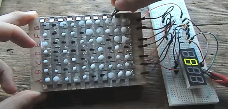
[Hales] has been on a mission for a while to make his own diodes and put them to use and now he’s succeeded with diodes made of sodium bicarbonate and water, aluminum tape and soldered copper. By combining 49 of them he’s put together a soda bicarb diode steering circuit for a 7-segment display capable of showing the digits 0 to 9.
He takes the idea for his diode from electrolytic capacitors. A simple DIY electrolytic capacitor has an aluminum sheet immersed in a liquid electrolyte. The aluminum and the conductive electrolyte are the two capacitor plates. The dielectric is an aluminum oxide layer that forms on the aluminum when the correct polarity is applied, preventing current flow. But if you reverse polarity, that oxide layer breaks down and current flows. To [Hales] this sounded like it could also act as a diode and so he went to work doing plenty of experiments and refinements until he was confident he had something that worked fairly well.
In the end he came up with a diode that starts with a copper base covered in solder to protect the copper from his sodium bicarbonate and water electrolyte. A piece of aluminum tape goes on top of that but is electrically insulated from it. Then the electrolyte is dabbed on such that it’s partly on the solder and partly on the aluminum tape. The oxide forms between the electrolyte and the aluminum, providing the diode’s junction. Connections are made to the soldered copper and to the aluminum.
To truly try it out he put together a steering circuit for a seven segment display. For that he made a matrix of his diodes. The matrix has seven columns, one for each segment on the display. Then there are ten rows, one for each digit from 0 to 9. The number 1, for example, needs only two segments to light up, and so for the row representing 1, there are only two diodes, i.e. two dabs of electrolyte where the rows overlap the columns for the desired segments. The columns are permanently wired to their segments so the final connection need only be made by energizing the appropriate row of diodes. You can see [Hales] demonstrating this in the video below the break.
One problem [Hales] has found is that the diodes are a bit slow, due to their capacitive nature, but there’s nothing he can do about that. However, another problem that he has attempted to solve but has yet to come up with a solution for is that the dabs of electrolyte dry out and need to be carefully rewetted. So while this isn’t a method for permanent diodes yet, we admire [Hales]’s persistence and inventiveness and if he keeps at it he’ll no doubt find a solution.
In the meantime, check out his previous experiments with copper oxide diodes. And if you want to see a steering circuit made with conventional diodes then we’ve previously talked about [Fran]’s circuit using a 555 and a 4017B decade counter to make a display count down to 0.
[wpvideo aoqf6WAe]


Now build an entire processor using this technology. :-)
Sadly I can’t build a whole processor, I still need off the shelf transistors.
If I can work out ways of getting these diodes to both run much faster and not dry out then I will try some more complicated logic circuits. Ions are already a few thousand times heavier than electrons and I’m operating at a much larger scale than commercial diodes, so I’m not in an easy street in for speed.
Can they not operate in some sort of sealed container that would prevent evaporation? I mean, I can see that the diode might just separate rather than dry out if it was sealed in something, but I figured I would ask.
Sealing the whole setup in a container (with a bit of extra water or a humid atmosphere) should work. Getting wires in/out would be solvable, but not being able to individually probe and test things out would be a bit of a pain.
Could you encapsulate the diodes in a resin or latex? I’d imagine a few coats of liquid latex would seal the moisture in
@wartoaster
It seems I can’t reply to your comment. I accidentally hit ‘report’ instead, which oddly seems to be a hair-triggered single click process.
Latex sounds like a very good idea. I’ll try it out, thankyou :)
This is really cool! Congratulations!
Thanks Ian :)
Insert lead or titanium wire/rod into one end of a silicon rubber tube sized such that it is a very tight fit, then add sodium bicarbonate paste via the open end and finally seal by inserting aluminium wire/rod of the same diameter as the inert rod. Experiment with the end geometries of both rods and their distance apart.
As for how the diode works, try finding out more about the electrical properties of NaAl(CO3)(OH)2 i.e. Dawsonite
http://webmineral.com/data/Dawsonite.shtml
It may lead you nowhere, but then again there is a high probability that it is forming at the junction. You can test this by using sodium hydroxide to strip the oxide off one diodes aluminium surface and heat to build up an oxide layer on another. If there is no need for Dawsonite to form then the oxidised diode will work as well or better.
Thankyou Dan, I’ll look into this.
This might suggest why I can’t build up the non-conductive layer using solutions other than bicarb soda or borax. A more complex molecule blocking reverse current flow would make sense.
Also: I have a feeling that dawsonite is an asbestos-related compound. This bodes well :P
Keep in mind that lead(II) sulphide crystals are semiconductors too and that is what the old crystal cat’s whisker diodes were made from, so you never know it could be the dawsonite in which case just synthesising the crystal and finding a good contact point may do, no H2O required.
If I operate these diodes when wet, then let them dry, they completely stop conducting. It sounds like you are suggesting a point contact setup, however. I’ll see how small I can make things and try from there.
I’m saying that if you can grow a big crystal you may be able to use it like other crystals used for diodes. While wet the solution may just be acting as a contact to the surface that the chemistry produces, so the H2O is doing two jobs, being the solvent for the initial diode formation, then being the solvent for the conducting solution that joins that diode to your external contact. I’d have to experiment with ionic liquids to see if the H2O was doing anything more important than that. That sodium rich glass mentioned in the new battery article the other day would be interesting, the solid electrolyte.
Yes: I’m imagining trying to develop a crystal between two very closely made contacts. That might be a bit hard, but identifying one white crystal from another white crystal might be harder.
Thankyou Dan :)
I’m not sure I’m imagining this setup the same way you are. Are you thinking of probing a single piece of bicarb paste with the very tips of both wires?
Wire->goop<-Wire, but in a tube so there is no H2O loss. The rubber tube lets you see what you are doing when you play around with the contact distances.
I’ve made point contact diodes before, but this is a whole other level. Very cool!
Your point contact diodes are still very impressive, especially since they can often be used to envelope AM radio into something listenable. That’s magnitudes faster than what I’ve made here :P
If you still have your point contact diode setup somewhere: try making a transistor out of it. I’ve recently bought and read “Instruments of Amplification” by H.P Friedrichs and he claims you can make them with a couple of fine probes positioned very close to each other.
That is essentially how the first commercial transistors were produced, except that grown and doped crystals were used instead of naturally occurring minerals.
In my case the diode consisted of a razor blade that had been heated up to form an oxide layer, and a needle lightly held against it to provide the contact point. It’s not nearly as impressive as it sounds.
I did look into making a point contact transistor, but it was a bit more complex than I had time for at that time.
No matter my level of dian barrage, I still think a rusty razor blade decoding worldwide communications is very impressive. It’s just a shame they’re fiddly.
Up next: Someone makes a ROM-based computer out of a mountain of these. Man, home-made diodes are cool.
The logic core is the easy part, it is the memory that is hard.
For the core you don’t need many diodes at all, for a Universal Turing Machine (e.g. rule 110).
000 – 0
001 – 1
010 – 1
011 – 1
100 – 0
101 – 1
110 – 1
111 – 0
Even better, fire acts as a diode too. Something about the ionic flow within the flame, but you actually can put two wires in a flame, one above the other, and put an AC wave the bottom one and get the half-wave rectified (and attenuated) signal on the top one. No flame = no signal. Pretty badass, apparently that’s how some flame sensors in furnaces and water heaters work. I did it with a PSoC like 10 years ago for a demo.
http://www.sparkbangbuzz.com/flame-amp/flameamp.htm
I always thought using bicarbonate as a diode would be a fun home experiment (it’s also done with borax). Apparently it makes a pretty good rectifier of mains current, and the aluminum glows if viewed in the dark. I remember hearing about a facility somewhere that had only relatively recently switched to a more modern approach to rectifying AC, but my recollection of the details are hazy. I want to say it was some power plant or railroad in England, but I’m unsure.
Great info on borax and bicarb diodes here:
http://www.sparkbangbuzz.com/els/borax-el.htm
I’m completely confused as to how this circuit works. Both strips being aluminium? Perhaps there’s a chemical race condition and things somehow polarise \\o/
My low voltage experiments with this setup did not yield anything like a rectifier. Perhaps magic happens at higher voltage (along with the glow magic).
The placement of the bicarbonate spots didn’t make sense until I realized he used non-standard assignments for the segment labels a-g.
What? Oh bugger. I thought this was how it went.
In that case, please don’t look too closely at my RJ45’s.
It seems, that a BCD to 7 seg. arrangement would also be possible.
I don’t believe this would work, atleast without decoding the BCD into the one-line-at-a-time setup I’m already using.
Diode matrices are not a fully addressable LUT, you need a decoder first.
Fix: put a drop of UV epoxy over the water droplet and zap away to cure. Also handy for insulating the rest of the parts, and other general repairs such as reattaching itty bitty wires to torn-off vias because someone used plumbing tools to repair an ipad.
Hmm. Even if I have the wet bicarb under constant UV, and drop the UV epoxy on, I’m not sure that this would properly cover the whole surface.
I’ll see if I can steal some from a friend.
So, there have been vacuum tube diodes and solid state diodes… is this the first version of the liquid state diode?
Haha, don’t forget flame state diodes.
http://www.sparkbangbuzz.com/flame-amp/flameamp.htm
Fire, air, earth, water.