Small DC motors are easy to find — you can harvest dozens from old printers and copiers. You might even get a few with decent gearboxes too. But will you get exactly the motor with exactly the gearing your project needs? Unlikely, but you can always just print a gearbox to get exactly what you need.
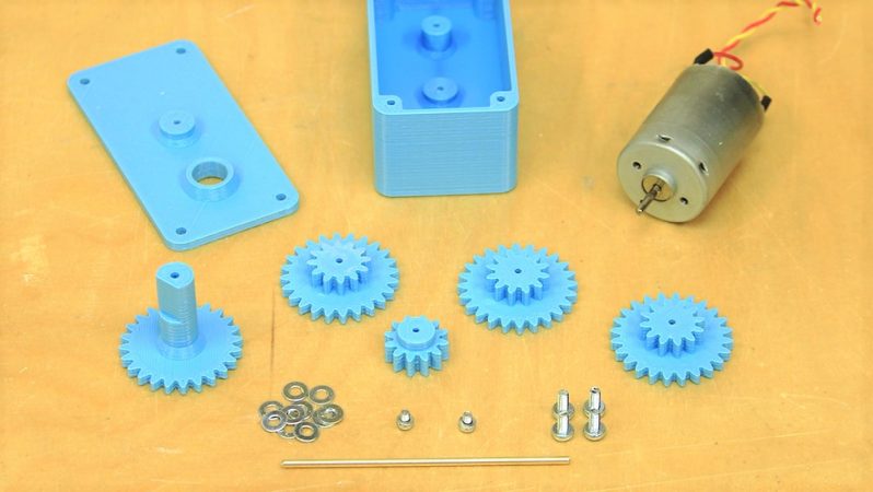
There’s nothing fancy about [fortzero]’s gearboxes. The motors are junk bin specials, and the gears are all simple spur gears 3D-printed from PLA. There are four gears in the train, each with a 2:1 reduction, giving a 16:1 overall ratio. The gears ride on brass shafts that are press-fit into the housing, and there’s not a bearing in sight — just a few washers to keep the gears spaced apart and plenty of grease. Despite the simplicity, the gearboxes turned out to be pretty capable, lifting a 3.5 kg load. The design files are available and should make it easy for you to get just the ratio you want for the motor you have.
Of course more complicated gearboxes are possible with a 3D printer, including a split-harmonic planetary gear, or a strain wave gear using a timing belt. No 3D printer? No problem! Just build a LEGO gearbox.


Really elegant and nicer than I could ever model or build… Just makes me nervous how the plastic on plastic output shaft will handle the radial load over time. Seems like that would be a good spot for a bearing.
Very nice! I just got my printer back up and running, and I have need of a gearbox for a different project.
I was sort of hoping it would be OpenSCAD or parametric so I could customize the ratio with no effort, but this is still great.
make it lift 30lbs without changing enclosure size.
Those gear teeth don’t look like involute profiles.
Take a closer look then.
I really hate cleaning up parts off the 3D printer – I want to do as little as possible from bed to usage. So for parts like these, I often put a small (0.5mm) chamfer on the bottom edges of the parts so that the first layer, which often winds up oversized a bit, doesn’t interfere in the assembly.
Yes! I do the same, it’a a great way to prevent getting those nasty edges on the bottom of the print. Actually I put the chamfer on both sides, top and bottom, it looks and works better for me, prints assemble and work with each other significantly better in general.
Plenty of grease – whaaat… I’d personally go for graphite on these things. Then again, commercial plastic gears are nearly always smeared with a untidy lump of white grease, so there must be something about it that beats graphite.
That white goo is usually lithium grease.
Looks like a nice gearbox, as long as it’s used within its limits. Ideal for when you need a specific ratio for a light duty project. PLA on PLA might last quite well, with a grease that doesn’t attack the plastic.
I’d want steel pins, and make the output one longer so it better supports the output shaft. Definitely not for any sort of fighting robot, the output shaft would snap at a layer first thing. I’d model an open structure inside it for filling with epoxy or urethane resin.
nylon would be ideal but does require a somewhat higher printing temp, same goes for petg.
if you can live with a little wear abs works fine as well, we ran a 1/4 hp electric rc motor through a printed abs gear, it does wear quite a bit though, at least when driven till hot to the touch.
You can also buy small plastic gears and shafts in bundles from ebay or other china shops. They’ll be a lot cleaner than printed ones.
I’m having trouble printing the output shaft and gear. It prints poorly at the intersection of the chamfer at the bottom of the shaft and the rest of the shaft. It breaks veriy easily there. Ive printed it by itself and with both Cura and Slic3r with the same result. Anyone else having the same problem? Anyone have a fix?
THE DESIGN IS AWFUL IT BREAKS !!!!!