There are two radio modulation schemes everyone should know. Amplitude modulation changes the amplitude — or ‘volume’, if you will — of a carrier frequency and turns all radio into channels owned and operated by a church. Frequency modulation changes the pitch of a carrier frequency and is completely run by Clear Channel. Amateur radio operators are familiar with dozens of other modulation schemes, but there’s one hardly anyone touches. Phase modulation is weird and almost unheard of, but that doesn’t mean you can’t implement it on an FPGA. [nckm] is transmitting audio using phase modulation on an FPGA (Russian, here’s the Google Translatrix).
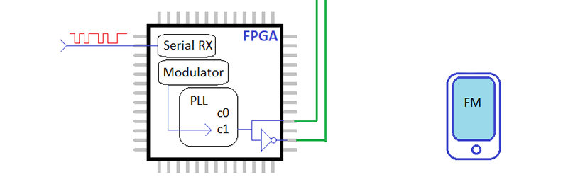
This hardware is just an Altera MAX10 board, with a single input used for serial data of the audio to be transmitted, and two outputs, each connected to a few bits of wire for a quarter-wave antenna. No, there’s no output filter or anything else except for a few bits of wire. It’s an experiment, chillax.
The Verilog for this project receives an audio signal as serial data in mono, 22050 BPS, 8-bit unsigned samples. These samples are fed into a dynamic PLL with phase shift in the FPGA. Shifting the phases also changes the frequency, so [nckm] can receive this audio signal with the FM transmitter on his phone.
Is this really phase modulation if it’s being received by an FM radio? Eh, maybe. PM and FM are closely related, but certainly distinguishable as modulation schemes in their own right. You can grab [nckm]’s code over on the gits, or check out the video demo below.


I’ve always heard that phase modulated signals are easily demodulated with FM because the act of changing the phase looks the same as changing the frequency to the demodulator. I know a lot of people in counter-surveillance who used to say that “the feds use phase modulation because you can’t detect it”, which has obvious flaws about detection but they thought that PM was some form of black magic radio on top of that. I only barely bothered trying to educate them before I realized how paranoia and stupidity really like to hang around each other a lot; not exclusively but definitely a lot more than paranoia and intelligence do.
Apologies for bumping in near the top of the comments list but phase modulation and frequency modulation are very simply linked both mathematically and practically in the design of an FM broadcasting transmitter. When I were a lad both designs were in use in broadcast transmitters. For the phase modulation version ( I hope I remember correctly) the transmitter input audio had to be put through a 6dB per octave high pass circuit which was kind of handy because the noise reduction system in use boosted the high frequencies of the input audio at the transmitter and cut them at the receiver so you could do the transmitter high frequency boosting as part of the modulation scheme.
I am talking about valve (tube) circuits where the choice of modulation technique could be decided by one system requiring one or two more active components (valves/tubes) than the other. Today the reasons would be very different.
Weird and unheard of? QAM is the basis for modern Wi-Fi and uses phase and amplitude modulation.
https://en.m.wikipedia.org/wiki/Quadrature_amplitude_modulation
Yeah, basically this. I think you’d be hard pressed to find a communication device that does NOT use phase shift keying.
QAM was a thing very soon after the CD4046 Phase Locked Loop chip was made. There was another chip with less states though but it was not that popular. NE565 ??
This was a very transitional time for electronics. Chips of that era like the NE555, CD4046 PLL, op-amps and many others came to the market because manufacturers could fit more transistors on a die – Medium Scale Integration (MSI). This same die/transistor density lead to a huge transition to digital logic. This is about the exact time when analog electronics became less popular and less education was put into analog because digital was the up and coming ‘future’.
If you ask an *well experienced* engineer about old analog them they will know all the basic and have a ‘fair’ idea about op-amps but they will often be stumped about PLL unless they were involved in a specific application.
And yes QAM is still used quite a lot today, often in conjunction with other modulation schemes.
Seems to me that phase modulation is everywhere. What about modern digital schemes like Wifi OFDM? That is phase, amplitude, and frequency modulation all combined in the form of FFT/IFFT. I think of simple digital phase modulation as discrete changes in phase. Bi-phase modulation would be 180 degree change for example. I see what he is doing here as FM modulation which is a form of phase modulation.
Yup, in a move to squeeze more and more into less. Soon we’ll be using time-crystals (not to be confused with Folgers).
There was a time when QAM stereo was better than FM Stereo, I just hope HD goes away as fast.
Here FM has more stations for Jesus than commercial stations. Even our once AM only NPR station got a second FM license. Clear Channel is now known as I (cardoid symbol) / Heart Radio
“Clear Channel is now known as I (cardoid symbol) / Heart Radio”
… and is in a fatally abusive relationship with it.
Just look into the DVB-S for various phase shift modulation schemes.
“FM transmitter on his phone”
maybe, it’s a FM receiver on his phone ?
If you modulate one it does effect the other two. But it is very clear how similar FM and PM are below:
https://i.imgur.com/yCWMzvx.png
Ehm, “Amateur radio operators are familiar with dozens of other modulation schemes, but there’s one hardly anyone touches. Phase modulation is weird and almost unheard of …”
Really? Then why is PSK31 one of the most popular digital “modes” in HAM radio? It literally stands for “phase shift keying, 31baud”
“Phase modulation is widely used for transmitting radio waves and is an integral part of many digital transmission coding schemes that underlie a wide range of technologies like WiFi, GSM and satellite television.”
Unheard?
I do not understand how PM could be demodulated by an FM receiver. I suppose the signal can be received by an FM receiver but I do not see how it could be demodulated. With PM, the frequency should remain the same and only the phase should change, right?
If you examine the phase and frequency mathematically, you will see they are closely related. Infact, frequency is simply the derivative of phase. So to demodulate PM using an FM receiver, you can in theory just stick in an integrator at the end….
and to send PM with an FM transmitter stick a differentiator on the input
The integrator was encoded into the FPGA –
Analog => ADC => digital integrator => PLL (PM) => antenna => FM receiver => Audio
Note that there is no DAC in this process because it’s single bit.
FM has a local oscillator and either a PLL or slope detector. A slope detector is the most common.
A slope detector is a filter that offset to carrier frequency so that the further away from the center frequency the incoming signal is the more it is attenuated by the filter and this gives the frequency to amplitude conversion.
The filter design of the slop detector will equally respond to incoming signals phase *changes* but not the overall phase itself and this is why the signal was integrated before transmission.
The effect of integrator is to allow the transmitted digital signal to keep hitting ‘off phase’ so that it has an accumulative effect in an attempt to offset the fact that these minor phase changes are equal to a very small frequency change.
Because the end result is like a very small frequency change the resulting audio has a very small amplitude. This is then simply compensated for with the volume control. In the video you can hear him change to a ‘normal’ station and the volume is so high that the normal station is distorted.
Nice hack! I’m impressed. I want to play with single bit and FPGA for a sound chip and this is a number of *level up’s* from that.
Similar “single bit” FPGA projects Ive done before is a single bit delta sigma DAC with amazing audio quality thanks to the high clock speeds and digital power even in a low end FPGA..
An average FPGA can run ate upwards of 100MHz so audio should be no problem at all. Even some of the larger CPLDs I have here are around 300Mhz. So there’s lots of head room to try interesting things with audio generation.
You can’t really have a frequency without changes in phase. Hint: A really good FM receiver always uses a PLL to demodulate. The PLL can be realized in an FPGA with an NCO (like the author used) and a loop filter with a negative feedback to form a controlled loop.
I really should have continued a bit more on the PLL thought. I forgot to mention the mixer. Digitally, this is just done with a complex multiply. So, to demod FM, you take your NCO complex output and multiply that with the incoming complex signal, this is mixing. The output from the mixing product can then be low-pass filtered (loop filter) and fed back as an error signal to the phase in the NCO. This is what “locks” the NCO phase to the incoming FM signal phase. Once phase-locked, the “instantaneous frequency” of the NCO is the demodulated audio. Hopefully that might give a mental visual… Gotta think about spinning around that unit circle.
I dont think the author used a NCO. I cant see the NCOs working here as they horrific phase noise characteristics, and would almost always “cover-up” the actual audio sidebands. His audio sounds very clean. I believe he used the onchip VCO based PLL (He even mentions the maximum VCO frequency at the end). Im not sure tho.
I took a look at the code. He is calling it a PLL, but he is just using some DDS IP as an NCO. I’m not sure what you mean about the phase noise. You can create insanely good oscillators digitally with an FPGA. The phase noise will depend on the on the resolution of your phase accumulator and sin/cos tables. Xilinx tools also have Taylor series correction that can improve the output even further. Since he is connecting a complementary digital output to a couple of wires to form a dipole, I’m sure the harmonic output is all over the place for several hundred Megahertz. The reason that it sounds good is because it is FM. It always sound good if you do it right.
Oh, when you say NCO you mean a full fledge DDS? I had just had the MSB of the phase accumulator in mind. Unless you pass it through a LUT and then square it up later, it will be unusable for any analog work imo. That is why all DDS IC convert the phase accumulator into a sine and then back to square using a external comparator….Strange he calls and draws the DDS a PLL…..
Sorry, I just realized what you are saying. It must be an on-board PLL with VCO the more I think about it. I’m not familiar with MAX FPGA, but it would make more sense if it was a internal synthesizer.
The direct digital synthesis IP in Xilinx Vivado has an optional phase offset input for this exact application. It also has a streaming phase increment input option if you want to do FM as well.
hi, i need help, i’m trying to do a VCO in FPGA, can you help with the VHDL code.
hi, i need help modulation coding on vivado without error.