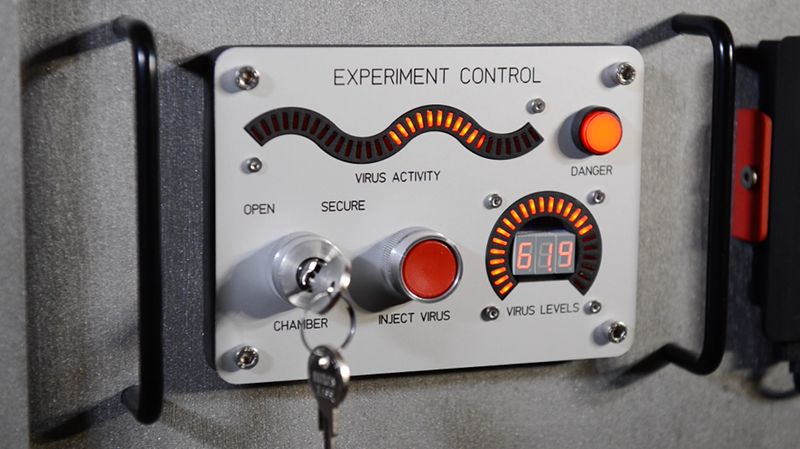
[BikerGlen] wanted to spice up his zombie containment unit (see video below) so he designed and 3D printed some very cool looking bar graphs. Apparently, you can get curved bar graph LEDs, but only if you buy a fairly large quantity. Hand soldering discrete LEDs at the perfect angle would be frustrating, but with a 3D printed jig, it was a piece of cake.
The devices use a MAX6954 LED driver, so it needs very few parts and takes commands via SPI. The chips were not cheap, but the small size and high integration sold [Glen] on it.
The rest of the story is trigonometry and PC board layout. The devices look great. If you want to see the containment unit in action, check out the video below.
We’ve seen bigger bar graphs, but none as attractive as these. However, we were wondering where the kill counter was on the containment unit.


I wonder why he didn’t use OpenScad to generate the LED Holders.
Mostly my familiarity with Matlab and Fusion 360 vs some of the other software out there.
Because OpenSCAD blows. There I said it. I wish it was better but it ain’t.
Select item, click Paste Special, Paste Array, Circular, specify item count and spacing in degrees.
Done.
Yeah… says you!
BikerGlen are you related to Brian Posehn
https://www.youtube.com/watch?v=phvbfs_kxrY
I don”t think so but now I’m going to have to watch this video.
This doesn’t look safe at all! How did he get access to the zombie virus? D:
Probably from the “darknet” – it’s said you can get anything out of it. :-)
Leaked NSA zombie virus. I think it’s something that even Microsoft cant make a patch for.
Haha! Yep, not safe at all.
That 4-color pilot indicator… Darns that’s sexy!
Does anyone have a type/number for this part?
Going from BikerGlen’s website – it’s an “Allen Bradley” “Cluster Pilot Light”. The images on his blog show 800T-PC416 and 800T-QC414 (see: http://www.ab.com/en/epub/catalogs/12768/229240/229244/2531083/Specialty-Devices.html – scroll down to find the cluster pilot light section with those two and more listed)
That’s them. PC416 is the four-color 120V version. QC424 is the four-color 24V version.
I love your use of those awesome industrial controls, [bikerglen]. Nice job overall, very impressive.
:thumbsup:
I checked out the YouTube for the project that’s using these 3D parts, and the how-to walkthrough just kept giving and giving!
A really well thought out and put together build. The DTMF control scheme was neat!
Thanks! I need to put together a blog post on the FPGA-based DTMF decoder too.
Thanks for the writeup so far! I don’t normally like videos, but I found myself watching till the end of that one.
There is quite a lot of evidence of planning, it really does show in the layout and structure of things. I wish I was as ordered, ha!
Yep, lots of planning…at one point I very roughly modeled the overall project in Fusion 360 just to try to visualize how different combinations and placements of switches / lights / wood blocks / 2x4s / etc. would look. Also Fusion 360 was great for checking for interference between all the industrial buttons and bar graphs before fabbing the aluminum panels.
Surprised there’s no comment on the fact that this is the second time this project’s development’s been on HAD; the allen bradley cluster mod was up last time: http://hackaday.com/2017/04/09/industrial-indicator-makes-the-move-from-plc-to-fpga/
All very tidy work,anyhow
Its really great, but does it really need so many parts on the electrical side?
It probably does I suppose… An FPGA?
Awesome though.
Thanks. There’s a lot going on…six 24V lights, two 24V pneumatic valves, four 5V LEDs on the cluster pilot light, four 3.3V SPI interfaces, a DTMF decoder, and an RS-422 serial port. Maybe 25 I/Os total? I initially planned to do everything on one big board with a 44-pin PIC24, an external DTMF decoder IC, and a bunch of transistors / relays, but I later decided to try to build my own DTMF decoder so I switched to the FPGA and all the PMOD-compatible I/O modules.
DTMF decoder chip + Atmel-based Arduino would probably do just as well. But if he has an FPGA dev board lying around, why not? And it’s good practice for his skills.
I look at this and think damn, Now i wanna make a custom rgb/rgbw magic eye for a stereo i am retro-modding (I would have restored it but it was gutted before I got it)
Thanks for your wonderful post. I am sharing this post.:)