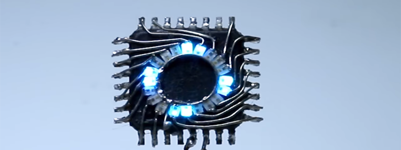
Sometimes the simplest things in life are the most beautiful. [The Tweaker] has soldered an LED circle on the top of an ATmega328P chip, and it looks great.
Using nothing more than some solder, wire, 20 x Pico 0402 (1mm x 0.5mm) blue LEDs and an ATmega328P (7mm x 7mm), [The Tweaker] managed to cram 20 LEDs into a circle on the top of the chip soldered in dead bug style. The chip is running some Arduino code and is operating on the 8 MHz internal crystal oscillator, so that manages to keep the part count low. The soldering is done in a spiral so the LED terminals are hooked up to the right pins, but it seems to add to the aesthetics of the project and looks like it would take a really steady hand. Once you connect a power source it displays chasing lights as well as other light patterns.
There may not be much to this project but it does look great.
You might be interested to read, this isn’t our first dead bug Arduino.


I’ve always appreciated when art and circuitry meet… That’s actually really nice looking!
Jim Williams
<3
Nice work! Definitely got some mad skills in order to solder 0402 LEDs and make it look nice.
Well that’s a level up on “flash that LED”.
hacksaw the die or maybe use a couple of decade counters and make it smaller.
Eh can be done with a few SMD transistors to make it even smaller.
There is no internal crystal, only an internal RC-oscillator. Why would you need external crystals if there were internal ones…
Fixed.
The internal oscillator is far less stable and more jittery then an external crystal.
Fail, read that wrong…
Needs and “edit” button!
Dude awesome and his soldering skills,
This is pure art!
Lovely. a decoupling cap would be nice though.
Why? Decoupling caps are a good rule of thumb as they avoid a number of ugly issues with power supply transients. His design clearly works as designed and isn’t doing anything critical and clearly isn’t a mass production design. Additionally, there is one. At the bottom of the chip just to the left of the power feed. It relies on the internal chip connections which isn’t great practice, but again, it obviously works.
Not just a good rule of thumb. A good way to prevent really buggy behavior. Thanks for pointing out the capacitor, though; I didn’t see it until you pointed it out.
I’m also wondering if there is any integrated resistor in the 0402 package of the LEDs, or if the AVR’s output buffer does all the current limiting (it should have a ~50Ohm output resistance, that could be enough for a blue LED and the MCU powered at 3.3V).
I had the same question, but I think the forward voltage of the blue led is just to high so no excessive current can flow
Yes, the outputs on the ATmega328P DO have built-in current limiting. Lots of AVR designs take advantage of this to avoid the need for extra components.
Not sure this is correct. Where in the datasheet do you see an option to enable current limiting on GPIO pins? Or are you considering the output resistance of the driver the “built-in” limiting?
man-x86 mentions ~50 ohms output resistance for this IC, but relying on that can get you into trouble in some cases, and its possible to easily exceed the max Vcc current spec if you are driving many GPIOs at their max current.
JustMe: Well, I THOUGHT the AVRs mentioned specifically some current limiting on the output pins, but now I can’t find it, so I may have been thinking of another product line. You definitely can determine the source resistance by measuring the slopes of the V/I curves shown in the “Typical characteristics” section, and it does come out to somewhere in the 40-50 ohm range, and you can then limit the duty cycle based to get the average current into a legal range.
Capacitors resist voltage change by storing and then releasing static charge. Inductors sore energy magnetically and the collapse of the magnetic field releases energy.
The twisted wires for Vcc Vdd are just as effective for decoupling as a capacitor.
No it’s not. It’s the exact opposite of effective. The effects of parasitic power rail inductance is the exact thing that decoupling capacitors are designed to ELIMINATE. They are bitter foes, not allies.
With circuits, you want to keep a constant voltage no matter how erratic the current is, and digital chips have VERY erratic current demands. The parasitic inductance wll tend to maintain a constant current no matter how erratic the voltage fluctuations are on the power rail, which is the exact opposite of what is desired.
Thanks for taking the time to post your comments. As someone without an EE degree, this was very informative. Wondering if what you discussed is in the The Art of Electronics that I just bought. Time to clean off the bench and dig in.
Thanks
Never read the book, so I don’t know. I did leave another comment below addressing more of RÖB’s misconceptions. Give that a read too.
The twisted leads add both inductance and capacitance. As the above post explains, the inductance is a bad thing. The capacitance of the leads is probably 1pF or so and is far too small to help.
Parasitic power rail inductance is not the same thing in fact it’s the complete opposite as there is no magnetic coupling in parasitic power rail inductance.
Actually the magnetic field is the problem, so while putting the wires next to one another reduces the magnetic field through partial cancellation, twisting does nothing to help other than keeping the wires close. The twists are there to reduce interference.
The “partial cancellation” reduces the inductance of the wiring, which is very beneficial even if you ignore the effects of interference
It’s amazing that something as simple as twisted wires is so poorly understood. I suppose the days understanding analog are gone.
Lets go back to the basics.
Cat4 etc uses twisted wires to achieve higher frequency data rates.
LVDS uses twisted wires to attain higher data rates.
HDMI uses twisted wire to attain higher data rates.
What this means is twisted wires pass higher frequencies.
A decoupling capacitor shunts higher frequencies.
Twisted wires transfer those higher frequencies to the other end where they are shunted bu the low output impedance of the power supply.
If you want to further improve on noise reduction you can add a decoupling capacitor at the power supply end.
Twisted wires are like an opposing wound transformer and *nothing* like two independent series inductors.
It’s not “amazing” at all, because transmission line theory is quite hard and easily misunderstood. You’re misunderstanding things quite badly here.
To say that twisted wires “pass” higher frequencies is such a VAST oversimplification it verges on stupidity. For one, it conflates the transmission of a signal with the transmission of power. The two situations have very different requirements and will have very different solutions.
A brief review: The reason decoupling is so necessary for CMOS digital circuits, is because they take their current is gulps. While static they draw very little, just leakage currents through the MOSFETs. It is when they switch states that the gate capacitances need to be charged and discharged, and during that brief period of time there is a very high impulse of current. The amount of charge that moves might be small, but it needs to move very quickly.
Off topic, this is why reducing the frequency of a microcontroller reduces it’s current usage. A lower clock speed means that less flip-flops are happening per second, so average current usage is lower.
The short impulses of current are a very high frequency signal. When the transistors switch and try to pull the surge of current from the power wires, their parasitic inductance limits how quickly the current through them can change. This causes the voltage at the chip’s power supply to sag while the inductor charges up current. In the worst case, this brief voltage drop can be low enough for the chip to brown out for a moment, which can cause any number of weird and erratic malfunctions that you will pull your hair out trying to debug.
The problem is the inductance of the power wires. Twisting the wires does not in any way reduce the iductance of the wires, so it doesn’t help the problem any. That’s the reason why you need a capacitor, and you need it as close to the chip as possible. The capacitor acts approximately like a voltage source for those brief surges, and placing it physically close to the chip minimizes the parasitic inductance between the chip and capacitor. This greatly reduces the magnitude of the negative voltage spikes and prevents the chip from browning out during a state change.
Twisting your power wires DOES NOT in any way help decouple the power supply. It does nothing to help or hurt the issue. It does nothing. You need a capacitor for decoupling. Do I make myself clear?
Congratulation, you have now confirmed that analog theory is very poorly understood.
Transmission line theory is not at all relevant as it relates to much lower frequencies than what we use decoupling capacitors for.
My explanation was not intended to be highly accurate. It was intended to be simple and by definition simple is NOT specific. That doesn’t make me stupid. If anything you comment is more reflecting of yourself.
Your comments about gulps of power consumption are also irrelevant. Decoupling capacitors store very little energy. What you describe is more about the much larger capacity that you place before a voltage regulator. You did however hit the nail on the head with switching transients.
Then unfortunately you fell right into the trap of believing that twisted wire is like to independent inductors. This is not the case as I explained in a previous post. 1/( 2 x Pi x f x c) is not the formula here.
Gotta chime in here. Sorry RÖB, but you’re just wrong. I understand that it can be difficult to back down from an argument, but continuing down this path will only result in further proof of your misunderstanding, and I suggest your best option is to do some reading before continuing to argue on this subject.
Analog circuits are VERY well understood, which is why we have software out there that can accurately simulate analog circuits, including things like microstrips and other wire features and how they behave at very high (and higher) frequencies. People have been designing circuits for the better part of a century that depend on this understanding. Look at the circuit boards for UHF instruments built from the 1950s and on, and you will see many amazing examples of this.
Unfortunately, analog circuits are also very badly MISunderstood by many people, which may be what you really meant, but this is a reflection on individuals, not the state of the art. This can be remedied by education, which in turn depends on people realizing that their understanding is either incomplete or just wrong. I ran into this myself in writing a comment in a recent HAD article regarding orbital dynamics. I started pontificating, then realized at some point that what I was trying to prove was in direct opposition to observed facts. Lucky for me, I reached the realization before posting my comment, saving me from considerable embarrassment. But this is how we learn.
MarkRD is right in stating that the twists in twisted pairs have very little effect on the signals passing through them. The reason twisted pairs are used (especially in multi-pair cables such as Cat 5 cables and plain-old-telephone-system bundles) is that what little radiation there is from a differentially-driven pair of parallel wires gets further reduced by the radiation from each half-twist being out of phase with the half-twists adjacent to it. In other words, twists in twisted pairs affect ONLY cross-talk between pairs.
As for the need for decoupling capacitors in CMOS circuits, MarkRD is also dead-on in this area. Just read the datasheets and application notes from almost any manufacturer and you will find this very well described. MarkRD’s explanation of this in his comment is better than I could do, so I would suggest you read his comment again very carefully.
“My explanation was not intended to be highly accurate. It was intended to be simple and by definition simple is NOT specific.”
There are good simplifications that can help improve people’s understanding, and there are bad ones that can confuse it. Yours is a bad one because it is trying to draw parallels between two different phenomena that are not even remotely similar or analogous. Signal transmission is a fundamentally different problem than power delivery, so the techniques involved will be very different.
“Your comments about gulps of power consumption are also irrelevant.”
It is impossible for it to be more relevant, because it is precisely that which makes decoupling capacitors necessary.
” Decoupling capacitors store very little energy.”
They don’t have to. The surge might have a very high level of current, but the time is so brief that very little net charge flows. The larger electrolytic capacitors are meant to stabilize the power rail against larger load trasients. They perform a similar function, but on different scales of magnitude.
“Then unfortunately you fell right into the trap of believing that twisted wire is like to independent inductors.”
It’s not a trap if it’s true. Twisting is not the same as turning, and won’t cancel the self-inductance of the wires.
“This is not the case as I explained in a previous post. 1/( 2 x Pi x f x c) is not the formula here.”
I certainly agree that that is not the relevant formula. It doesn’t do your argument any favors when you bring up the formula for capacitive reactance when the discussion is about inductive reactance.
Ho god I LOVE IT.
I wish I had the time. My list of things to do is so long.
wow
I love seeing old school skills reborn. Nice work, and on small parts too!
Encased in acrylic would make a cool necklace.
Great enhancement. Then use the wires to connect it to a coin cell holder, on the back of the wearer’s neck. Or the battery could be mounted to the back of the chip, but then it would be harder to replace.
I’ve seen LED event necklaces that have a two-piece battery holder: one piece holds the batteries (three hearing aid alkalines) and a neodymium magnet, the other piece just has a magnet. This serves as both a closure for the necklace and a power switch. Neodymium magnets are plated with a metal which makes them conductive. Like this: http://images.jebolist.com/CTprofiles//CA01-04-0044/021.jpg
This inspires other options:
* Use a neodymium magnet to hang it on your earlobe (assuming the coin cell has a steel case).
* Ditto, on your nose.
* On a piece of clothing.
Yep, got my wife a led crystal necklace a few years ago. Uses something similar to that for the batteries.
Impressive. Just wow. I was even more impressed when I saw what you couldn’t see in the picture at the top of the article: the whole thing being supported only by a couple of thin wires.
Now, I would have put a decoupling cap on it, but then, I would have hidden it on the back side of the chip, which may be what [The Tweaker] did, now that I think about it.
When I saw the Blue LED’s and the small form factor first thing I thought of was the startrek TNG/DS9/Voyager medical tricorder dongle for scanning/sensing when the doctors use it to scan a specific area of the body. This idea could be used to do such a thing for cosplay and such or making reproductions etc for such things.
Yup that would work.
Added modification: if the diodes are RYGB then it could be modified to change colour as well as circulate.
With Arduinos as long as the protection resistors are added on each pin you can safely drive in charlieplex mode and minimize number of wires.
Also ideally use 35 gauge microsolder (63/37) to reduce stress on the fragile LED wires and install 0402 SMD resistors on the junctions, then multistrand twisted clock wire for the Atmega to resistor leads.
That’s really cool – thanks!
damn. Encase it in clear acrylic, put that on a chain and wear it like a pendant.
i still see unused pins, they’d better not be gpio’s !
Why not? Easy to turn on pull-ups or pull-downs with modern microcontrollers, which eliminates power dissipation on floating signals. I/O pins are meant to be left unconnected if not used in this day and age.
uh yeah, i was actually joking about the fact that those unused pins should have had a purpose, like a 4bit DAC, or a single pin PWM doing some audio.
Ah. Ok!
I knew your were joking. :)
He could have used the two unused crystal pins as GPIO, and added two additional led. But there is no way to use digitalWrite on those pins without creating a new “board” in the Arduino IDE.
The other unused pins are reset, ARef, Avcc, GND, ADC6 and ADC7 (the latter two are analog input only).
So other than adding a button to the bottom, to change modes, he took it to the max.
Could you imagine if led dies were embedded into microcontroller packages with a clear window much like old eproms? It would be useful just as a debugging tool to not even need external status indicators … plus it would look sweet. Probably not practical but it would be pretty cool.
Now that would be awesome. :)
Can you imagine what it would do the the unit cost, adding extra dies (since LEDs need different semiconductor processes than CPUs) and a transparent lid? And THEN it would be a matter of choosing the number and type of LEDs that would be the most useful to the most customers. And when that failed, because you really CAN’T satisfy most of the people most of the time, then the customers who DID design these into products would be left high and dry.
What has made microcontrollers very practical (and very cheap) today has been the fact that the most-requested peripherals could be added without greatly increasing the die size. And the peripherals included on microcontrollers have been pretty universal – UARTs, timer/counters, ADCs.
Maybe a better approach, if size is really a major factor, is piggyback modules, i.e., packages that are the same as the standard microcontroller packages like the TQFP-32 but with taller legs.
I was imagining it more for developers as built in debugging status indicators so color wouldn’t matter, either way it’s not practical but would be very cool. Something like current photo-optical packages with integrated control circuitry (much like the ws2812 serial LED packages). One can always dream …
That could only be more inpressive if it also displayed the time.