[Perry] was interested in adding a 4th axis to his CNC machine, but not very excited at the prospect of spending hundreds of dollars on the parts and electronics to make it work. There is a very clever and very inexpensive way to add a 4th axis to a CNC machine, though, and after a bit of fabrication, he was able to add a ‘rolling’ 4th axis to his machine.
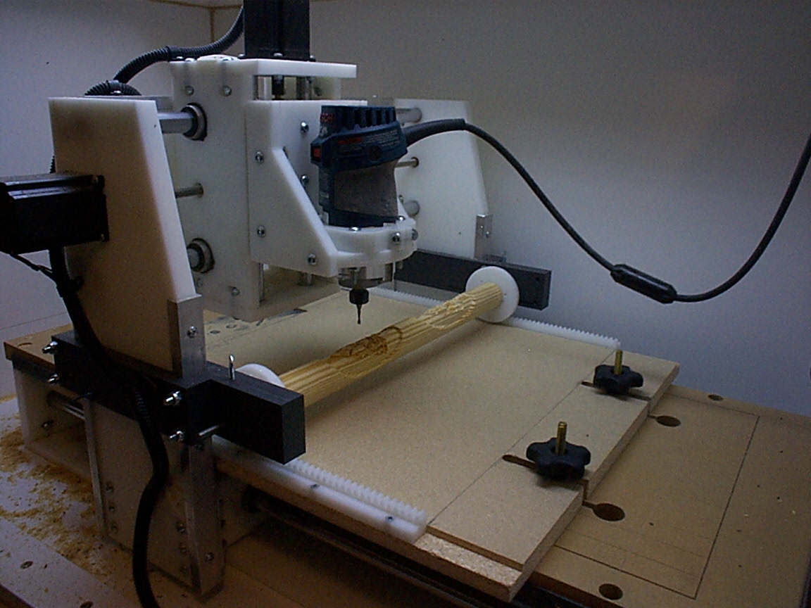
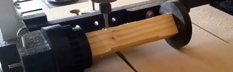
[Perry] took one look at [Bob]’s project and decided this would be the perfect build to get him a 4th axis. The parts for this build were fabricated out of black HDPE, with the only real change to the design being a ‘variable length’ 4th axis. Instead of two rack gears mounted to the bed of the machine, [Perry]’s build only uses one rack, with the other end simply rolling on the bed.
There are a lot of clever inventions that don’t work, so what’s the verdict with this CNC hack? It actually looks pretty good. [Perry] was able to turn some square stock into round stock, and able to engrave a spiral around a cylinder. You can check out those videos below.


This is kind of funny, because you sort of do it like this in Mastercam, too.
Surfcam too.
My initial thought was that it looks like an overengineered lathe but on second thought I realized you could make some asymmetric designs. I like it but it needs to be higher off the bed for thicker materials. That said, there are some really cool five and six axis CNC machines that are much better and I’ll never be able to afford. ;)
You can rent machine time, but you probably need insurance. Numbers I have heard are 50-80eur/h, 1500 eur/annum.
Look at the link and there’s a video of him making a dodecohedron with it, something you absolutely couldn’t do on a lathe :)
Neat!
Rather than a 4th axis, isn’t this more accurately a 3 axis with 2 Cartesian and 1 polar?
correct, afaik there aren’t that many accessible CAM tools that support more than 3 axis at a time anyway
Exactly, it’s a different third axis.
Just looking at the image I thought the cleverness was that the 4th axis was independent from the Y axis and that the tool could somehow push the roller around to control the 4th axis. With some smarts this could actually be doable with about the same complexity, would just need a way to lock the roller angle when it’s not intentionally being rolled.
Cool as hell, but not really a fourth axis. Just a different third axis.
As pointed out, this is really just a 3-axis machine with one being rotary instead of linear. A true 4-axis machine can do things like bore holes off of the centerline of the workpiece; this one cannot.
Still, it’s a clever way of getting rotary carving on a limited budget if you don’t need real 4th-axis capability.
Awesome idea :)
10 years ago some guys used the same technique to laser etch a pumpkin
https://www.youtube.com/watch?v=SDqTp33xjME
That is simply brilliant.
I’m wondering if you could use the tool end to press on a mechanism which rotates the work piece just a little. Then move your tool over the work piece using full 3 linear axis like normal. Then rinse and repeat. This would give you a proper 4th axis usong only the 3 motors. Locking type gears would help.. eg a worm gear.
I like it!
Only problem i see is keeping dust away from the wheel and sprocket? Otherwise the z-axis will be varying.
Similar idea to something I was making five years ago, only mine was for lasers.
https://www.youtube.com/watch?v=bpABBpIhO4M
https://www.youtube.com/watch?v=QSieTZYH9yo
It’s a rolling lathe. Could be better, could be worse. Still interesting.
Author mentions in this article that moving the Y axis causes the workpiece to rotate, surely we all know that the Y-axis from math is vertical- so therefore this statement is wrong. It should say the X-axis or z-axis (depending join interpretation.
In CNC machines and other machinery such as industrial robots, Z is almost universally the vertical axis. X and Y fall on the horizontal plane, like drawing on paper in math class.
The Y axis “from math” can literally be in any direction that makes the math convenient.
You could make a small version of this, and sell it for decorating Easter eggs. Make a small fortune.
You could call it “Egg Bot”.
Oh wait…
This is really cool. I hope you don’t mind if I adapt this to my little 3 axis CNC/Laser engraver that I just bought to do engraving on the turned pens I make. It only has a 6 x 9 inch work area so its quite small compared to yours. I was going to draw it up first but I’m more of a hands on type of guy so I just jumped in and started designing each piece as I go. I’ll let you know how it goes.