For the longest time, Zener diode regulators have been one of those circuits that have been widely shared and highly misunderstood. First timers have tried to use it to power up their experiments and wondered why things did not go as planned. [James Lewis] has put up a worth tutorial on the subject titled, “Zener Diode makes for a Lousy Regulator” that clarifies the misconceptions behind using the device.
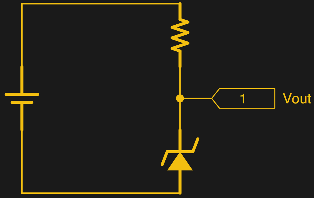
[James Lewis] does an experiment with a regulator circuit with an ESP8266 after a short introduction to Zener diodes themselves. For the uninitiated, the Zener diode can operate in the reverse bias safely and can do so at a particular voltage. This allows for the voltage across the device to be a fixed value.
This, however, depends on the current flowing through the circuit which in turn relies on the load. The circuit will work as expected for loads the draw a small amount of current. This makes it suitable for generating reference voltages for microcontrollers and such.
To make a Zener into a “proper” voltage regulator, you just need to buffer the output with an amplifier of some kind. A single transistor is the bare minimum, but actually can work pretty well. You might also add a capacitor in parallel with the Zener to smooth out some of its noise.
Zener diodes are wonderful little devices and write-ups like these are indispensable for beginners and should be shared more often like the Zener and Schottky Tutorial and Diodes as a Switch.


Any device used properly makes for an excellent product.
“More Zener Regulator Problems
This entire exercise was to show why the Zener diode is a lousy regulator. The voltage drop depends too much on the current flowing through the junction. Which means the “regulator circuit,” depends on a constant load. Any active device is going to cause the VOUT node to be unstable.”
No.
If you have peaky current requirements like a radio would have, add a friggin capacitor across the zener. The error in the design was not that zeners make crappy regulators but in not realizing what the actual current requirements of the radio were, don’t check the current for the radio with a meter, check it with a scope across a 0.1 ohm resistor on a 10x probe. Then you will know the peak current requirements for your circuit. From that you can calculate how much capacitance is necessary to hold up the voltage for your peaky current load.
” The voltage drop depends too much on the current flowing through the junction. Which means the “regulator circuit,” depends on a constant load. Any active device is going to cause the VOUT node to be unstable”
Not sure what he means. As long as Izt is met, the Vz of 3.3V will be met unless the zener diode overheats from power dissipation. If the Vzener node is 0.9V or 1.8V and your zener is 3.3V and at least Izt is available then your series resistor value is too small.
The RESISTOR in his circuit is dropping too much voltage, not the zener diode. He should have put a 0.1 ohm resistor in-series with the zener anode to ground connection and another one in series with the ESP8266 ground connection, and measured the voltage drop with a scope. He would have immediately seen where the current was going and what his actual problem was.
This article was not indispensable as it provides incorrect usage and information about the part.
I agree with the article author that a circuit using a Zener diode could be used as a voltage reference (although the Zener breakdown will generate noise of its own, so your capacitor is again recommended).
I certainly agree with you that a Zener diode could be used in the typical Zener regulator circuit, but it would be slightly more helpful to point to his mistake.
In his example Vin=5V, Vout=3.3V=Vz=3.3V Pz=0.5W.
When the load is drawing no current for a prolonged time (hence irrespective of [lack of] capacitor) the current through the Zener diode must equal the current through the voltage dropping resistor. The maximum current for this Zener diode is roughly: Izmax=Pmax/Vout=0.5W/3.3V= 152mA. This is also roughly equal to the maximum supported current for the load (instantaneous load current if not using a capacitor, sustained average current when using a capacitor, determining the timescale).
In order to maintain the correct voltage when the load is not drawing any current, the voltage drop must be 1.7V for the above current Izmax so the resitance should be Rs=(Vin-Vout)/Izmax=1.7V/152mA= 11.22 Ohm
It seems the author made his mistake here: for some reason he divides my ~60mA (the current he measured for the load), from measuring using the resulting 28Ohm he knows the resistance should be lower, but fails to locate the mistake. He tries 10 Ohm less (18 Ohm) but the voltage is still poorly stabilized.
As you note he should use the correct resistance, and a capacitor.
Later on he notes the load actually draws up to 200mA, so the Zener diode is in fact not suitable for sustained 200mA (a capacitor won’t fix this). Either a Zener rated for a higher power, or substitute the single Zener diode with 2 zeners in parallel to double the maximum current capability. In that case however, the new Izmax=1W/3.3V=304mA, and hence the resistor would need to be halved to 5.61Ohms…
The article is not “indispensible” at all, but I would think it’s more practically helpful for a lot of newbies than 90% of the other Zener regulator posts out there.
Re: your capacitor smoothing solution. Have you tried it with an ESP8266? My guess is that you will discover that you need an inconveniently large cap, or face the high quiescent currents that the OP is (perhaps implicitly) afraid of.
See the pass-transistor circuit linked in our fine article, and read my comments below for more. And please try to stay constructive, or at least civil.
I don’t guess, I measure.
I’m with you Elliot on the ‘useful article’ and ‘constructive points’.
” And please try to stay constructive, or at least civil.”
Seriously?
On a 0,1 Ohm resistor you can safely use the probe in 1x mode. You do not need the current waveform up to the MHz range, this kind of current spikes has to handled by a capacitor anyway.
How about:
Evad’s Zener Diode Indispensable Article:
[1] Specify your maximum input voltage requirements.
[2] Specify your minimum input voltage requirements.
[3] Specify your maximum load current requirements.
[4] Specify your minimum load current requirements. This might be micro amps for a device that will go to sleep. This might mean, that the minimum load current is << Izt of the zener, meaning that it is of insignificant value.
[5] Compute the Resistor value at minimum input voltage and maximum load current + Izt of the zener.
R = Vin(min) / (Izt + Iloadmax).
[6] Compute the Resistor's power requirements at maximum input voltage and maximum load current:
P_dissipated_res = (Izt + Iloadmax) * (Vin_Max – Vzener).
[7] For safety, ensure that your resistor's power rating is at least 2x the maximum expected power to be dissipated.
[8] Compute the zener diode's power dissipation requirements at maximum input voltage and minimum load current:
I_Resistor' = (Vin_Max – Vzener) / Resistor.
P_dissipated_zener = (I_resistor * Vzener)
[9] Choose a zener diode that will meet your Izt and power dissipation requirements.
You’re right of course, in theory. And we all know that there’s no difference between theory and practice, in theory. :)
In practice, max load on an ESP8266, depending on the source’s output resistance, will require a resistor in the single-digits. That’s step 5. Somewhere around step 6 or 7, you realize that dissipating 1/2 W all the time isn’t reasonable. If you actually make it to step 9, you’ve failed the reality check.
So you’re right, and that is exactly what 90% of the Zener regulator tutorials on the web look like, but the circuit is a bad match for the OP’s problem. And if you read between his lines (reference vs. regulator) that’s what he’s saying.
No,
That’s not what he said, or what the purpose of the article purported to be both here and on Hackaday. Look at the article title on here?
His problem was not understanding what his current requirement was. If he used a 60 mA LDO he would have the same problem.
Why would dissipating 1/2 watt all the time not be reasonable? Was that one of his circuits requirements?
Do 90% of the zener articles on the web tell you how size a zener for vin max, vin min, iload max, iload min, the power dissipation of the resistor, the power dissipation of the zener, or do they misuse the part and state that you should rethink a lever using the approach?
The only trouble between theory and practice are the theories derived from bad practices.
Sometimes the easiest answer is the simplest one. Which is where Zener diodes fill their niche wonderfully….
Here is a practical example out of the telecom world, where the battery voltage is -54 to -42VDC. Seems that most security devices, especially smoke detectors have a working Voltage range of 9 to 32VDC. The standby current draw of a smoke detector is in the uA and goes to many mA when in alarm. Wholesale price of a DC-DC converter with terminals and a metal case is about $11. A 28V 5W Zener costs much less, and takes up less space too. It is wired in series with the Smoky. Out of thousands of installations, we have experienced only a handful of smoke detector failures which is in line with their own mortality. Bigger issue is installers wiring the diode the wrong way (for a variety of reasons usually related to confusion with the positive ground battery) which results in only the traditional 0.7V drop. The Smoky can last up to a month operating at 54V which is good on them… but they do overheat and eventually fail. Imperative QC to check the Smoky’s terminal voltage to ensure the Zener is eating 28V. And these cell sites do get hit by lightning too…. no issues.
Most smoke detectors operate between 9 and 32V because they are intended to operate off of FACP systems that are backed up by 1 SLA (12 – 14V system) or 2 SLA’s in series. (24 – 28V system).
I don’t understand how a fire inspector would approve an installation of fire protection equipment that is powered from non-fire rated equipment. Telecom gear is not fire-rated. Is your example in the US?
Maybe it’s different if the intent is to give a warning of trouble rather than saving lives? As in some equipment releasing the magic smoke e.g. the infamous Rifa caps.
If the fire starts as a result of the power system failure (short circuit), then the smoke alarms will be disabled. It’s rather dumb to power a fault alarm from the actual devicery it’s supposed to be monitoring.
Most residential smoke detectors in the UK run off mains, with a battery backup. (Some older or DIY install ones are battery only.) Good ones are wired for interconnect anyway.
I believe ours run on 230VAC, each with their own regulator, though it’s possible they slipped in a central reg for them somewhere when I wasn’t looking.
So running them as described here is fine, provided they’ve got individual batteries.
Hard wired smoke alarms with no backup battery are common in the US, my parents house had one and my current apartment has one. I have supplemented their hard wired hallway smoke detector with my own battery powered ones in the bedrooms.
If only it were possible to wire it up such that the signal on means “OK” and loss of signal means “FAULT”…
680 AHr (or more). Capable of thousands of Amps short circuit current. Any faults get cleared through the load circuit breakers. Hundred’s of AMPS are required to open battery breakers. But since it is a one space installation… a shelter… the smokie will go off first… and if a legitimate fire, eventually the site will loose it’s transport links to the outside world. In reality, sites have been lost when the building they sit on burns down… and they alarm properly right until the end… or the forest burning around it lights up the shelter.
If the cell site is on or in a building and must have a fire detection connected to the building, then that is done to code. Environmental alarms are required at every site… door… temperature… fire… AC power, tower lighting status, generator, etc. So the requirement is to let the Telco’s own 7×24 monitored control center know what is going on. There is no requirement for a UL approved and monitored system at every site…. but read on….
On leased space in an existing building, fire and building codes apply… that usually requires a 6VDC emergency light or exist sign for escape purposes. Due to code, it is supplied, but… it lasts a couple hours if the battery is new, while 48VDC lighting on the station battery will last 8 hours. Similarly, in a power outage, the building’s own fire system will run it’s batteries down much sooner than the batteries in the cell site.
Zenner diodes are just fine, [James Lewis] simply does not understood how to use them properly, so his conclusions are wrong. Calling that a “worth tutorial” is embarrassing.
Hackaday, please peer review your blog post before publishing.
:o(
Two things. I basically agree that there’s not much meat here — one man’s realization that a simple Zener diode regulator probably wasn’t for him.
On the other hand, if you read around on the web, which is what another newbie is going to do, you’ll see lots of tutorials that cover Zener regulators, and the entire advice on picking the resistor is simply “according to current demands”. They’re going to be in the same boat.
The real problem here is that an ESP8266 is a very peaky load, and to supply the max current, you need such a small resistance that 95% of the time you’re going to be dumping a lot of heat in the Zener, killing your battery tout suite. A straight Zener+resistor regulator is a horrible solution here, no matter the resistor value.
I was the editor who added in the reference and link to the Zener + pass transistor circuit, precisely b/c it actually solves the OPs problem for 10 cents more on the BOM. The transistor’s beta multiplies the effective maximum current, allowing a factor of 100-300 lower quiescent current (95% of the time with an ESP — this is a big improvement) while still meeting the peak current demands.
To reiterate, the point is not that the OP picked the wrong resistor. It’s that picking the right resistor to drive a peaky load with a Zener alone is impossible. Pick the right circuit, and all is well.
Is the Zener in the pass transistor circuit serving as a voltage reference rather than a regulator? This is semantics, but it’s certainly in the spirit of the OPs post. So I’d claim that it’s not entirely worthless.
Sheesh!
Thanks, that’s helpful. Might be good to move the meat of this comment up into the article for those of us who’ll find the article in a years time.
Probably should have! We _did_ gently suggest the transistor solution in the article, but didn’t get into the full detail about why. Heck, my comment above is longer than IP’s writeup, but is basically summarized in the phrase “buffer the output”.
This would be an awesome collection of circuits to try out on the bench. Parts are all dead common, except for the Zener. Plug it up to an ESP8266 (through the 3.3 V pins if it’s already got a regulator built in) and put the voltage rails on the oscilloscope. Watch them sag. How big a capacitor will be needed to get the ESP over the hump? How about with the transistor in the circuit? Good real-world experience, for a few cents.
BTW: I play around with the ESP-14s a lot, which have a STM8 microcontroller and an ESP8266 inside. I wanted to be able to turn on and off the ESP’s power supply with a pin from the STM8, but every time I turn the ESP back on, it pulls the rails so low that it resets the STM8. There’s going to be power supply circuit that makes this work, but I still need to play around more. So yeah, my comments on the ESP and regulators are borne of (sad) experience.
If your STM8 resets when it switches on a load, there are two possible problems. The power supply pins of the STM8 should be better isolated/decoupled from the system power line and the even bigger problem is that most designers simply don’t ever think about adding a capacitor on the controller reset near the controller pin.
Of course, if by switching on the load you create a longer primary power failure thanks to large secondary capacitors, you should try to use some soft start switches that can handle a slower, current limited charge up of the secondary capacitance.
i used one as a reference voltage for a from scratch smps. a 555 provided the switching frequency, an opamp in comparator mode would compare the reference with the output (through a voltage divider that sets the target voltage). a discrete and gate made from a couple transistors would take the output from the comarator and the square wave off the 555. the output of that was fed into a mosfet which provided the switching. the rest was the inductor, diode, and capacitor in the buck configuration. held 5v all the way to 500ma. not the best regulator but it worked. great if you want to learn how smps works, not so great as an actual supply.
also used zeners for double ended adcs when i needed the output to center on a certain voltage. they are also sometimes capable of shifting down logic levels. better than a divider worse than a mosfet.
Zeners are good enough for reference voltages. Using this reference voltage one can make a good power supply either a linear one or a switching. Using the simplest regulator that one can make with a zener and discrediting the whole thing is far away from right.
This “Arduino generation” knows nothing…
… yet.
A lot of people have entered the hobby, coming in from a software background rather than an electronics one. They do lack the basics of electrical engineering, and they will make beginner mistakes. But the more they share their experiences, the faster they’ll learn and get over them.
Mocking them for not knowing what you already know is like mocking a toddler for falling while he’s taking his first steps. It’s not cool.
Post a better circuit or keep your negative thoughts to yourself.
+1
Those of us who come from a code background don’t rip into hardware folks for bad code.
At least, not here.
Dailywtf serves that purpose.
thats because hardware people write better code. the software people you run into these days use a virtual machine and piss away all their performance.
also i really dont like the distinction between hardware people and software people. if you dont know some of both you wont have any hope of being good at either.
There’s nothing wrong with a toddler falling while he’s taking his first steps, and, indeed, that’s not something to laugh at. I do find it rather laughable, however, to tout that as a worthy lesson for aspirant marathonists.
Also, I think there’s a huge difference in attitude between reporting/sharing an experience, even one that resulted in failure, and writing a tutorial. If you’re writing a tutorial, one would presume that you know what you’re talking about, that you have the baggage to back up the authoritative tone a tutorial has. If you don’t, then you’re being presumptuous in writing it.
I fail to see how such a “tutorial”, with bad premises and bad conclusions, can do anything to advance anyone’s knowledge. As such, it is anything but “indispensable”.
The arduino can be seen like a stepladder for a baby, so people just learning to walk can fall on their faces from an elevation.
I’ve used them in a simple low current application. My favorite is with PNP transistor in emitter-follower design. Vsource to collector, resistor from collector to base, zener diode in reverse bias from base to ground. Diode needs to be at desired output voltage plus 0.6v. Lastly, a capacitor somewhere to handle ripples. Emitter provides regulated output. Not efficient but works quick if I need something and I can’t carry my bench power supply along.
In this emitter follower configuration you need an NPN transistor for positive output voltages. But I did not use this circuit for a long time. If I need a regulated output voltage normally I use at least a 78xx – or just a suitable battery if I cant take the lab PSU or a switch-mode plug pack.
Zener regulators?
Could’ve done it with a 555!
An overdriven zener diode can function as a light source. (for a very limited time) I remember making that mistake as a kid playing around with these things, stupidly trying to force the voltage down from a sturdy power supply of a considerably higher voltage. :-)
Glad to read I wasn’t the only one;)
I always have seen zener + transistor combo. Never zener diode itself. This more to learn theory of the zener diode. This is in my conscious 30 years of electronics.
he might have had more success using two zeners in series (forwards) to drop 1.4V.
the esp probably works fine with 3.6V :D
otoh, if all else fails, make a resistive voltage divider with a no-load current of 10+ times your load. just watch the resistor ratings.
also, talking about incredibly clever solutions for a simple problem, for non-permanent cases, put a D cell in series with the esp but in reverse. 5V-1.5V = 3.5V…