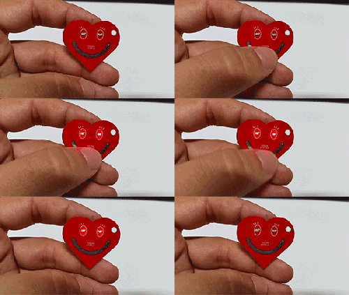
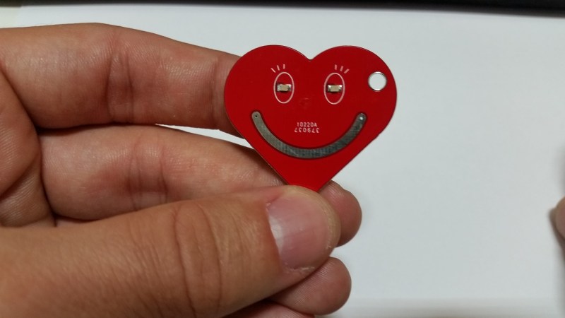
Sometimes the simplest projects can be the most impressive. Most of the time our simple projects are not as neat and elegant as our more time consuming ones. Sometimes they don’t even leave the breadboard! When [Sasa Karanovic] first envisioned his key-chain idea, he knew it would be simple. But he made up for the lack of  sophistication with style.
The heart-shaped key-chain has one goal – to flash a pair of red LEDs when a capacitive button is touched. He was able to accomplish this with a PIC12LF1822 and a handful of supporting components. We’re quite impressed with the soldering skills and layout of the PCB. The resistors, LEDs and single capacitor are 0603 surface mount devices, which push the limits of hand soldering. [Sasa] gives a great explanation of how capacitive touch buttons work and how they can be easily incorporated directly into a PCB.
What’s the smallest SMD you’ve soldered? Let us know in the comments, along with what you think about this nifty key-chain.


The smallest discrete component I’ve worked with while hand soldering would be a 0201 resistor while the smallest pitch would be a 0.4mm DFN. Components that have a line of pins are dealt with by tacking one or two sides to the PCB and then drag soldering the rest with a big tip. Component size/pin pitch is practically irrelevant when the option to reflow is available.
As far as attaching wires to leads of a component goes, the smallest I’ve gone is about 1mm pin pitch.
I give kudos to this nice repair job: https://imgur.com/gallery/Amt1b
Similar here. The hardest parts I soldered by hand were some QFN devices with 48 pins and 0.5 mm pitch, those are a PITA. After that, you love to solder 0201 resistors again!
0603 pushing the limit of hand soldering? HaD definitely loves bold statements.
0201 maybe is, but basically I use 0402 most of the time as it’s still easy to solder and rework multiple time.
That’s really cute and innovative!
Thanks! I’m glad you like it. It was one of those weekend project that you do in couple of hours for fun.
“a handful of supporting components”
Small hands too
An old Snickers commercial claimed “a fistful of peanuts in every bar!”
yeah, right!
“The resistors, LEDs and single capacitor are 0603 surface mount devices, which push the limits of hand soldering.” You guys think that 0603 pushes the limits of hand soldering? This is the standard size I use. I’m sometimes soldering 0402 components, which is a little tricky. I’m also sometimes soldering SOD523, which are a little smaller than 0603, but have smaller pads. I have soldered 0201 components once or twice, and that’s hard. I still have yet to try and use my 01005 resistors (which I have).
The worst thing I’ve ever soldered was for my picosumo about 5 years ago. That’s a 10x10mm board, populated by QFNs and 0402 components with extra small pads.
The most extreme SMD soldering i did so far was 01005 (0.4 x 0.2mm) with hand soldering. That was for an RGB-LED watch with 1x1mm RGB LEDs on one side and all the brains and sensors (CortexM0, accelerometer/magnetometer, LiPo-charger, RTC) and passives on the other. PCB size came down to a 32mm circle. Did even push my luck a little by using a small 9DSBGA package for the LiPo fuel gauge. Just need some more time to get the firmware completed.
0402 is basically standard everyday stuff as I rework and build up a lot of prototypes with that size on my dayjob. 40-pin connectors or QFNs with 0.5mm pitch are not really a problem either
I do use a good binocular microscope for that work tho. Did try some of these USB-Microscopes to do some work, but the image lag, and general low depth of view and lack of “3D” vision compared to a binocular view got me right back to the optical instrument.
“a handful of supporting components”
The smallest I ever soldered where the diodes on my Ergo Dox http://studioidefix.com/assets/images/ergodox/ergo1.jpg and adding wires to the firmware chip of my ThinkPad X200s to flash coreboot https://libreboot.org/docs/install/images/x200/wson_soldered.jpg (mine looked uglier but worked after the 5th try).
The smallest I ever soldered where the diodes on my ergo dox and some wires to the firmware chip of my ThinkPad X200s to flash libreboot.
http://studioidefix.com/assets/images/ergodox/ergo1.jpg
https://libreboot.org/docs/install/images/x200/wson_soldered.jpg
My standard is 0603, bare hand, bare eye.
Sometime 0402, it’s not that hard.
I solder QFN by hand too, but I then check with a thread counter lens.
But honestly, doing it for prototyping is fine, for (even) small batch, it’s worthless.
Smallest one I’ve hand soldered is a 0603 myself. Haven’t tried anything smaller.
I’d be concerned if someone actually put this on a keychain. The exposed battery terminals could short against the other keys/keyring or other junk in your pocket/purse. This could cause a thermal event (fire) and/or possible battery damage and acid leakage.
Additionally, I would be concerned with continuous activation running the battery dry. This is why there’s a proximity sensor on phones to turn off the interface when they are put into a pocket or holder.
Sorry to be a negative nancy, but the usage scenarios are important to consider during design.
The handful of tiny exposed locations would be difficult to bridge for any length of time. Also, this is a coin battery, not a high current (or capacity) lithium cell: http://data.energizer.com/pdfs/cr2016.pdf
If you’re still worried, it would be easy to put some clear fingernail polish or similar over the components and test points.
On your second point…spurious button presses could be mitigated in software, but look at the schematic and the micro’s datasheet, and do the math on the current draw. One battery is going to last a *very* long time. Plus, these batteries are less than $0.25/ea in modest quantity from China.
Thanks RB for explaining.
Also to give another perspective, this was a weekend project, not something you would want to sell, mass produce or even consider hard to make. This was a weekend project and main goal was to add some “cool factor” to boring old keychain.
And I definitely agree that with CR2016 I would expect fires coming out of you keychain. Especially if you take into the account number of exposed points that you can short, and CR2016 max current draw.
Battery life is completely dependent on your FW and how you set up your active vs sleep times. And I don’t expect someone to play with their keys 24/7.
Thank you Hackaday for sharing!
This was one of many weekend projects that I did and my goal was to make a unique gift that you can gift to your loved ones and they would be thinking of you every time they see it. I think from that perspective, this project does a good job of capturing that. However from electronics perspective, this project is just slightly more complex than blinking an LED, but it’s still pretty cool for anyone getting their feet wet with electronics. That’s the reason for 0603 components instead of 0201. MCU might be a bit harder for novices but it’s still relatively easy to hand solder but for sure will give you better reliability than SOIC and also saves a lot of space, because I didn’t want my loved ones carrying a motherboard on their keychain. :)
There is a lot of room for improvement and for different variations of the design, that’s why I’m thankful to Hackaday for sharing this project and can’t wait to see what will the DIY community come up with. Happy hacking! :)
what a beautiful key chain i want to buy this . I like the design anfd color of your key chain . I love to collect different style key chains and i love buy one from you.
Awesome one helpful reply. good !