The vast majority of desktop 3D printers in use today use one or more lead screws for the Z-axis. Sometimes you need to think outside of the box to make an improvement on something. Sometimes you need to go against the grain and do something that others wouldn’t do before you can see what good will come out of it. [Mark Rehorst] had heard the arguments against using a belt drive for the Z-axis on a 3D printer build:
- The belt can stretch, causing inaccurate layer height.
- If power fails, gravity will totally ruin your day.
He decided to go for it anyway and made a belt driven Z axis for his huge printer. To deal with the power loss issue, he’s using a 30:1 reduction worm gear on the drive — keeping the bed in one place if power goes. And after a few studies, he found the belt stretch was so minimal that it has no effect on layer height.
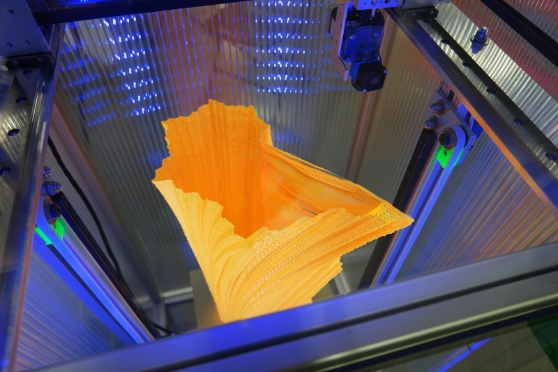
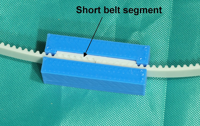 Of course those two issues are but a small portion of the overall ingenuity that [Mark] poured into this project. You’ll want to see it in action below, printing a vase that is 500 mm tall (took about 32 hours to get to 466 mm and you can see the top is a hairy wobbly at this point). Luckily we can geek out with the rest of his design considerations and test by walking through this fantastic build log from back in July. Of note is the clamp he designed to hold the belt. It uses a small scrap of the belt itself to lock together the two ends. That’s a neat trick!
The introduction of a belt driven Z-axis eliminates Z-axis wobble — an issue that can be exacerbated in tall printers. Desktop 3D printers are constantly improving, and we’re always excited to see a new trick work so well. Let us know if you’ve seen any other handy Z-axis modifications out there.


Congrats Marks!
Thanks! MMS FTW!
Any accumulative errors further away from the plate?
I calibrated the Z axis step/mm by running the Z axis over 650 mm of its length, so it prints very accurate vertical dimensions in prints. The belt stretch plus torsion in the drive shaft is about 42 um/kg of print mass, which works out to about 1.2um is a 250 um layer of PLA that completely covers the 300×300 mm bed, a pretty unrealistic printing scenario.
Yeah, I’d say that’s perfectly acceptable. Congratulations on doing the math and determining your margins instead of reasoning by analogy that it would never work! I see a lot of that going on with 3d printing and lots of other fields, too. People reason out what will and won’t work in their head instead of actually experimenting in reality. It has its place, but it’s fairly limited.
Belt stretch and chain cogging are two things that people constantly bring up that are never near as bad as people say it is.
And as an addendum, the people who talk about chain stretch are the absolute worst
Indeed, timing belts are fiber-reinforced and don’t stretch at all in practical terms
Absolutely. Hell, when I was cutting belt for my new printer I noticed it had about eight steel wires running through it. That isn’t going to have any appreciable stretch if it’s tensioned correctly. People probably have slop in their idler pulley or motor setup and are mistaking it for belt stretch because they instinctively feel that the belt is stretchier than the acrylic frame. But they’d be wrong.
Agreed, never had that and been 3D printing for four years, only going to be buying a new printer because my old K8200 is very low res compared to printers these days.
Looks Nice. I would of had a nice Printer like that…BUT
I had it sitting outside my work shop ( in the early stages of putting it together.) and my wife wanted to talk to me. She leaned on it and bent my rods and everything that was connected to them.
I was in shock!!!!
To this day I could not tell her about what she had done. And yes If she had done anything else that day she would not be in this world anymore.
So So sad. But I Luv her.
Luv and forget.
I did notice on the picture that the print was even moving. I like the width but I think the print is to wobbly.
Nice work I like how you put things together.
And yea I’m still waiting for my new controller to come in for my printer. I keep making the magic smoke come out from.
I think I learned my lesson.
Not sure which one you though was moving, but the orange one was 500 mm tall and had single wall thickness of 0.4 mm. It was too weak to support its own weight- lesson learned. The white one in the video has 1.2 mm thick walls. The print wasn’t moving at all. It’s an effect of the lighting inside the printer. There are two LED strips in the top of the machine and two long vertical strips on the front. When the extruder carriage moves the shadows shift around and make it look like the print is moving. The first time I saw it I thought it was the print moving, too.
Actually, yes the nozzle dragged a bit on the white print and the thin walls (1.2mm) allowed it to move slightly. That was entirely the print moving, the bed is rock solid.
it is really common for tall vase mode print to be wobbly…
If have had that for years! Two belts even ;)
https://cloud.ikhebeenboot.nl/index.php/s/qjkdpKEQ3X8eLsL
In your machine, just like screw driven machines, if the motors/screws lose sync the X axis tilts, requiring realignment for accurate printing. In my machine, both belts are driven by a single motor, so the only way they can lose sync is if one of the drive pulleys comes loose. Lock-tite prevents that. Since the bed moves in my printer, if the belts managed to lose sync the bed would tilt but the axes would remain orthogonal
In your machine the X axis probably doesn’t weigh much so it may not drop even if power is lost. The bed support and plate assembly weigh 3.5 kg in my printer, and it will hit the bottom of the machine like a sledge hammer (I know this from experience) if something isn’t done to prevent it from dropping. The worm gear drive completely stops the bed from moving when power is cut.
Belts for Z are nothing new,… I have a machine that I built 6 years ago that uses a belt Z. Also, CoreXZ machines use a belt Z. There are many many out there on the webs for years. WAKE UP HACKADAY
He is using a worm gear drive on a shared shaft, which is then driving dual Z belts. The worm gear drive should have been the point here, not the belts.
This is not a bad setup for a large build area printer as you could conceivably extrude several kg of material and still get away with using a single stepper for Z.
Backlash is also not a concern as you are constantly loaded in one direction.
You could even have the Z and horizontal axis controlled through one belt!
https://www.youtube.com/watch?v=nf1QQU0Eaqg
After running a delta and a few cartesian with screws I can confirm belts > cheap lead/ballscrews. I cant speak for C1-C5 class ballscrews though it is something I want to try on a delta.
East3d gecko is also using belt driven Z axis
Wondering why not use a decent distance sensor and a closed loop, instead of having super accurate positioning. I suppose it would slow things down perhaps and add to the cost.
Why don’t decent 3D printers have support for battery backup built in? Even a fairly small battery can run a 3D printer for quite some time.
https://www.youtube.com/watch?v=i-ksb-gzfyE
It seems to be as easy as setting the PSU to 12.3V or 24.6V (4.1V/cell which is the recommended “float charge” voltage for common lithium cells), then attaching a 3S or 6S battery via a BMS.
I connect my 3d printer to a normal UPS. that covers me against house power going out (which is quite rare, anyway). the unit runs from 12v and I can pick a quality 12v brick and that will be reliable. why should I have to do more? I must be missing something; what is there about ‘power loss’ that is not solvable with regular old UPS systems? are you talking about extended blackouts or just brownouts?
Once you want more than a few minutes of runtime, a UPS is surprisingly expensive compared to lithium batteries. And that’s not even counting conversion losses.
Using lithium cells is never that easy.
I think some printers might be OK for battery backup, but the printer in the article has a 750W line powered bed heater. You’re going to need a pretty big battery to provide as much power as it is going to use for any length of time under battery power.
It might be OK to provide a battery back-up that will allow it to operate long enough for a graceful shutdown in the event of a power outage. But really only useful if the controller’s firmware allows for bringing it back up and continuing where it left off. You’ll still have the problem of the print letting go of the bed if the bed temperature drops. Maybe best for printers printing on room temperature beds.
i am sure it has (mostly) to do with air shipping rules and regulations, items with a battery will have a hard time passing the customs check…
Since not everyone would actually want that feature (and those who do have different ideas on how much battery they want), it would just be a socket to connect a battery, not shipping a battery with the printer.
East 3D Gecko has applied this idea( core XY structure)
While I don’t have anything against this build, the assertion that doing this to eliminate Z wobble seems a bit like hyperbole. There are certainly tall printers that are using screws on Z with no issues.
A well constrained Z motion should not be susceptible to wobble, regardless of what the motivational force is. Perhaps a more accurate statement would be that it’s simply easier to get a wobble-free Z with belts than rods.
The most important thing to eliminate Z-axis wobble is frame stiffness. (Of both the machine frame and the print-bed). Everything else can be compensated or designed around, but if the foundation isn’t stiff you’ll need either very clever servo algorithms with sufficient position feedback accuracy or you’ll lose accuracy/repeatability.
I think the focus on Z-wobble is a bit overdone. But for a cursory comparison with screws, and considering the parts that go into most hobbyist builds, it is a valid feature. In most machines with relatively unrigid frames, belt lifting Z might actually be a benefit because there aren’t any lateral forces to resist with the typical 8mm end-supported guide rails.
The worm drive is a more interesting feature of the design. It eliminates having use motors with brakes (and a lot more torque), multiple reduction pulleys/belts that may introduce backlash, or Rube-Goldberg looking assemblies of counter weights, bungee cords, or any of the other crazy things people have done to control bed-drop.
The other more interesting part of this Z axis, and maybe I should have combined the blog pages on them, is the bed support and kinematic leveling system that has proven to be rock-solid. I have literally dragged the printer up my basement stairs, put it on its back in the car, driven across town, stood it back up and started printing with no leveling adjustments, and then the reverse of that, at least 5 times in the last 6 months.
The kinematic mount uses springs to hold the bed plate down on the leveling screw heads instead of using them to push the plate up against the leveling screw heads. The good stuff happens where the screw heads meet the underside of the bed plate. The reference screw sits in a chamfered hole and the pitch adjuster in a chamfered slot which allows the bed to be adjusted for leveling and to roll around the X axis after it is leveled with X, but prevents all lateral motion. The slot allows the plate to expand when heated and contract when it cools without causing anything to flex and without causing the bed to lift or drop. The third screw stops the roll when the bed is in the level position, and since it contacts the flat underside of the bed plate, the bed is free to expand and contract over it.
Finally, I think the Z=0 switch design is more interesting than the belt clamp. I needed a Z=0 endstop, and wanted something that allowed finer adjustment than simply using a screw to bump the switch, so I designed and built an assembly that has a levered cam that hits the switch, and effectively turns a 32 tpi screw into a 250 tpi screw, allowing for very small Z adjustments without overshooting because of coarse screw threads. I probably should do something similar for the roll adjuster…
+1
The worm drive deserved more focus than the use of belts.
Do you even need a stepper motor for the z axis?
It only travels in one direction, and if you make that direction down, i.e. lower the build platform rather than raise the print head, thus keeping the print head’s z position fixed at the top of the build volume, the motion is very simple (unlike the x and y motions obviously).
If you let gravity feed the z direction, and use a ratchet,gearbox and dampener to control the free-wheeling motion of the build plate towards the floor, you could simply wind the build platform up to its zero position, build layer0, click the ratchet to let the build plate down by a fraction that relates to your layer height (each lowering step click of the ratchet would need to be at most, half of your minimum Z resolution).
This gives the advantage that you don’t need a huge expensive stepper motor on the z axis, if you are aiming for a huge z axis. You can get away with something simpler, (a cheap brushed motor, or indeed a human being) to wind the platform back up for the next print.
If you keep raising the print head, as is the case with most conventional printers. then as the part gets heavier, this will require more and more effort. If you allow the built part to lower instead, then its increasing weight works to your advantage.
In theory, using this method, you could lower the build platform on cables, over a void, and build a part that is as tall as the length of the cable, or the depth of the void.
No doubt someone will have already tried this, and can tell me why it is a bad idea. :¬)
In most printers the Z axis moves in both directions during printing for Z-lift on retraction, a feature that improves print quality. That requires a precise mechanism so that the extruder nozzle returns to the exact same Z level when printing resumes. Even small errors result in visible print defects.
A spring or falling weight driven mechanism is an interesting idea…
I was working on a chocolate printer a couple years ago that would print on a rotating bed. The bed was mounted on a screw and lowered itself downward as it rotated. I might restart that project one of these days.
Amazing creation !! Any chance I could get the stl to your part cooling duct??