A 3D Printer With Quadruple The Output

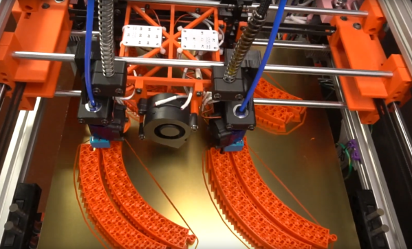
While the polygraph is colloquially associated with pseudoscientific lie detector tests, the actual invention of the first polygraph was designed to mechanically duplicate the pen strokes of someone writing. Famously, a polygraph was used by former US President Thomas Jefferson in his “modern office”, a replica of which still sits in the Smithsonian museum. Few of us have a need for a pen-based polygraph anymore, but inspiration from the centuries-old invention can still be gleaned from the machine, like in this 3D printer which can output four identical prints at once.

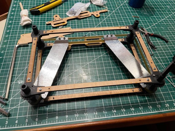
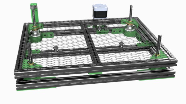
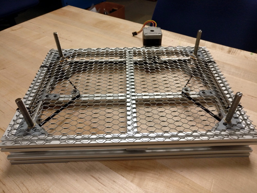
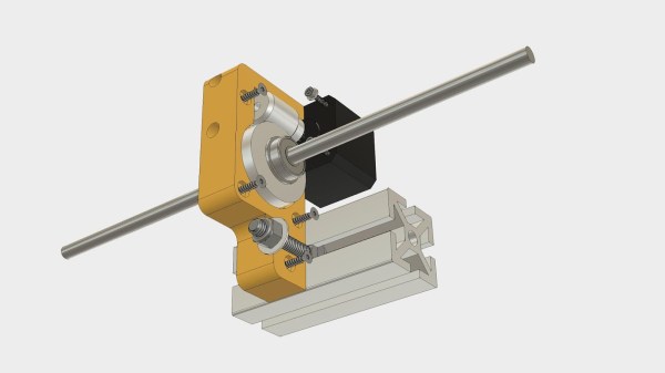
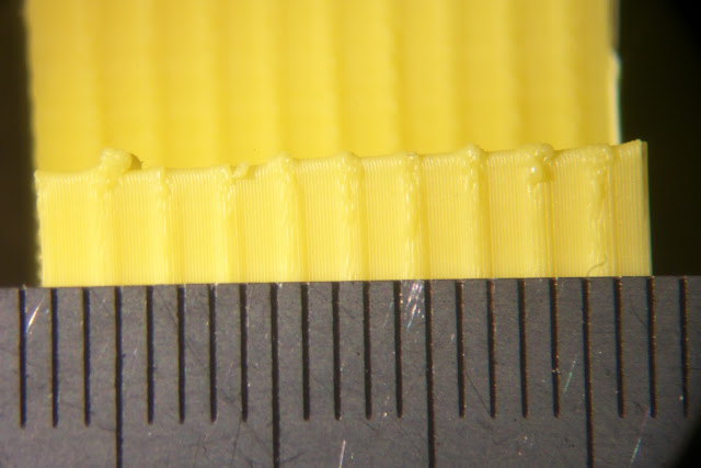
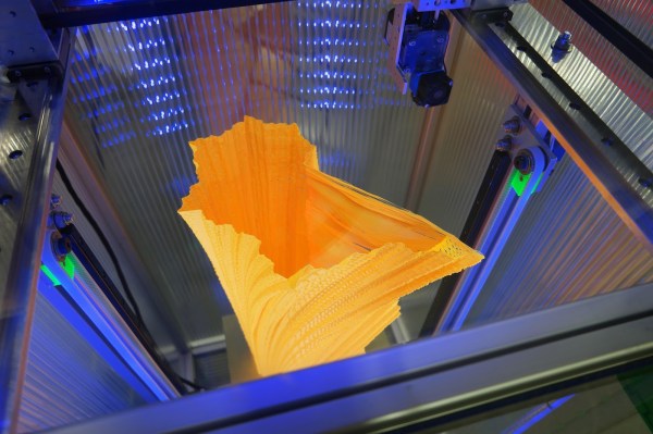
The printer is a Core XY design with four separate print heads, which are all locked together. The printer behaves as if there is a single print head which keeps it simpler than it otherwise could be. Some extra consideration needs to be paid to the print bed to ensure it’s level and flat, and it also includes a unique Z-axis designed to prevent Z-banding from poor quality leadscrews. It has a fairly wide print area, but a noticeable restriction is that it’s essentially quartered, so while it can produce many parts at once, it can’t produce a single part that uses the entire area of the print bed.

Every printed part used to make this printer was designed by [Rick] in OpenSCAD. He also built a custom electronics board with the printer drivers, and all other associated circuitry in KiCad. For anyone who prints large volumes of parts, this might be just the trick to increase output without having to manage more printers. If you already have more printers and need an easier way to manage them all, take a look at this dedicated Raspberry Pi set up to do just that.

Continue reading “A 3D Printer With Quadruple The Output”

Laser Z-Axis Table Comes Into Focus

Laser cutters and 3D printers are game-changing tools to have in the workshop. They make rapid prototyping or repairs to existing projects a breeze as they can churn out new parts with high precision in a very short amount of time. The flip side of that, though, is that they can require quite a bit of maintenance. [Timo] has learned this lesson over his years-long saga owning a laser cutter, although he has attempted to remedy most of the problems on his own, this time by building a Z-axis table on his own rather than buying an expensive commercial offering.

The Z-axis table is especially important for lasers because a precise distance from the lens to the workpiece is needed to ensure the beams’s focal point is correctly positioned. Ensuring this distance is uniform over the entire bed can be a project all on its own. For this build, [Timo] started by building a simple table that allowed all four corners to be adjusted, but quickly moved on to a belt-driven solution that uses a stepper motor in order to adjust the entire workspace. The key to the build was learning about his specific laser’s focal distance which he found experimentally by cutting a slot in an angled piece of wood and measuring the height where the cut was the cleanest.

After everything was built, [Timo] ended up with a Z-axis table that is easily adjustable to the specific height required by his laser. Having a laser cutter on hand to bootstrap this project definitely helped, and it also seems to be an improvement on any of the commercial offerings as well. This also illustrates a specific example of how a laser cutter may be among the best tools for prototyping parts and building one-off or custom tools of any sort.

This DIY Drill Press Is Very Well Executed

Plenty of projects we see here could easily be purchased in some form or other. Robot arms, home automation, drones, and even some software can all be had with a quick internet search, to be sure. But there’s no fun in simply buying something when it can be built instead. The same goes for tools as well, and this homemade drill press from [ericinventor] shows that it’s not only possible to build your own tools rather than buy them, but often it’s cheaper as well.

This mini drill press has every feature we could think of needing in a tool like this. It uses off-the-shelf components including the motor and linear bearing carriage (which was actually salvaged from the Z-axis of a CNC machine). The chassis was built from stock aluminum and bolted together, making sure to keep everything square so that the drill press is as precise as possible. The movement is controlled from a set of 3D printed gears which are turned by hand.

The drill press is capable of drilling holes in most materials, including metal, and although small it would be great for precision work. [ericinventor] notes that it’s not necessary to use a separate motor, and that it’s possible to use this build with a Dremel tool if one is already available to you. Either way, it’s a handy tool to have around the shop, and with only a few modifications it might be usable as a mill as well.

Continue reading “This DIY Drill Press Is Very Well Executed”

The Practical Approach To Keeping Your Laser In Focus

You could be forgiven for thinking that laser cutters and engravers are purely two dimensional affairs. After all, when compared to something like your average desktop 3D printer, most don’t have much in the way of a Z axis: the head moves around at a fixed height over the workpiece. It’s not as if they need a leadscrew to push the photons down to the surface.

But it’s actually a bit more complicated than that. As [Martin Raynsford] explains in a recent post on his blog, getting peak performance out of your laser cutter requires the same sort of careful adjustment of the Z axis that you’d expect with a 3D printer. Unfortunately, the development of automated methods for adjusting this critical variable on lasers hasn’t benefited from the same kind of attention that’s been given to the problem on their three dimensional counterparts.

Ultimately, it’s a matter of focus. The laser is at its most powerful when its energy is concentrated into the smallest dot possible. That means there’s a “sweet spot” in front of the lens where cutting and engraving will be the most efficient; anything closer or farther away than that won’t be as effective. As an example, [Martin] says that distance is exactly 50.3 mm on his machine.

The problem comes when you start cutting materials of different thicknesses. Just a few extra millimeters between the laser and your target material can have a big difference on how well it cuts or engraves. So the trick is maintaining that perfect distance every time you fire up the laser. But how?

One way to automate this process is a touch probe, which works much the same as it does on a 3D printer. The probe is used to find where the top of the material is, and the ideal distance can be calculated from that point. But in his experience, [Martin] has found these systems leave something to be desired. Not only do they add unnecessary weight to the head of the laser, but the smoke residue that collects on the touch probe seems to invariably mar whatever surface you’re working on with its greasy taps.

In his experience, [Martin] says the best solution is actually the simplest. Just cut yourself a little height tool that’s precisely as long as your laser’s focal length. Before each job, stick the tool in between the laser head and the target to make sure you’re at the optimal height.

On entry level lasers, adjusting the Z height is likely to involve turning some screws by hand. But you can always add a motorized Z table to speed things up a bit. Of course, you’ll still need to make sure your X and Y alignment is correct. Luckily, [Martin] has some tips for that as well.

K40 Gets A Leg Up With Open Source Z Table

If you’ve done even the most cursory research into buying a laser cutter, you’ve certainly heard of the K40. Usually selling for around $400 USD online, the K40 is not so much a single machine as a class of very similar 40 watt CO2 lasers from various Chinese manufacturers. As you might expect, it takes considerable corner cutting to drive the cost down that low, but the K40 is still arguably the most cost-effective way to get a “real” laser cutter into your shop. If you’re willing to do some modifications on the thing, even better.

One of the shortcomings of the K40 is that it lacks a Z axis, and with thick material that needs multiple cuts at increasingly deeper depths, this can be a hassle. [Aaron Peterson] decided to take it upon himself to design and build an adjustable Z table for the K40 at his local makerspace (River City Labs), and being the swell guy that he is, has made it available under an open source license so the rest of the K40-owning world can benefit from his work.

[Aaron] started the design with a number of goals which really helped elevate the project from a one-off hack to a sustainable community project. For one, he only wanted to use easily available commodity hardware to keep the cost down. The most complex components should all be 3D printable so the design would be easy to replicate by others, and finally, he wanted the user to have the ability to scale it in all dimensions. The end result is a electronically controlled lifting platform that anyone can build, for any laser cutter. It doesn’t even have to be limited to laser cutters; if you have a need for precisely raising or lowering something, this design might be exactly what you’re looking for.

The table is primarily constructed out of 15×15 aluminum extrusion, and uses standard hardware store expanded wire mesh as a top surface. Height is adjusted by rotating the four 95 mm T8 leadscrews with a GT2 belt and pulleys, which prevents any corner from getting out of sync with the others. Connected to a standard NEMA 17 stepper motor, this arrangement should easily be capable of sub-millimeter accuracy. It looks as though [Aaron] has left controlling the stepper motor as an exercise for the reader, but an Arduino with a CNC shield would likely be the easiest route.

We’ve seen a lot of hacking around the K40 over the last couple of years, from spring loaded beds to complete rebuilds which are hardly recognizable. If you’re looking for a cheap laser with a huge catalog of possible hacks and modifications, you could do a lot worse than starting with this inexpensive Chinese machine.

Fail Of The Week: 3D Printed Worm Gear Drive Project Unveils Invisible Flaw

All of us would love to bring our projects to life while spending less money doing so. Sometimes our bargain hunting pays off, sometimes not. Many of us would just shrug at a failure and move on, but that is not [Mark Rehorst]’s style. He tried to build a Z-axis drive for his 3D printer around an inexpensive worm gear from AliExpress. This project was doomed by a gear flaw invisible to the human eye, but he documented the experience so we could all follow along.

We’ve featured [Mark]’s projects for his ever-evolving printer before, because we love reading his well-documented upgrade adventures. He’s not shy about exploring ideas that run against 3D printer conventions, from using belts to drive the Z-axis to moving print cooling fan off the print head (with followup). And lucky for us, he’s not shy about document his failures alongside the successes.

He walks us through the project, starting from initial motivation, moving on to parts selection, and describes how he designed his gearbox parts to work around weaknesses inherent to 3D printing. After the gearbox was installed, the resulting print came out flawed. Each of the regularly spaced print bulge can be directly correlated to a single turn of the worm gear making it the prime suspect. Then, to verify this observation more rigorously, Z-axis movement was measured with an indicator and plotted against desired movement. If the problem was caused by a piece of debris or surface damage, that would create a sharp bump in the plot. The sinusoidal plot tells us the problem is more fundamental than that.

This particular worm gear provided enough lifting power to move the print bed by multiplying motor torque, but it also multiplied flaws rendering it unsuitable for precisely positioning a 3D printer’s Z-axis. [Mark] plans to revisit the idea when he could find a source for better worm gears, and when he does we’ll certainly have the chance to read what happens.

Huge 3D Printer Ditches Lead Screw For Belt Driven Z Axis

The vast majority of desktop 3D printers in use today use one or more lead screws for the Z-axis. Sometimes you need to think outside of the box to make an improvement on something. Sometimes you need to go against the grain and do something that others wouldn’t do before you can see what good will come out of it. [Mark Rehorst] had heard the arguments against using a belt drive for the Z-axis on a 3D printer build:

  1. The belt can stretch, causing inaccurate layer height.
  2. If power fails, gravity will totally ruin your day.

He decided to go for it anyway and made a belt driven Z axis for his huge printer. To deal with the power loss issue, he’s using a 30:1 reduction worm gear on the drive — keeping the bed in one place if power goes. And after a few studies, he found the belt stretch was so minimal that it has no effect on layer height.

Of course those two issues are but a small portion of the overall ingenuity that [Mark] poured into this project. You’ll want to see it in action below, printing a vase that is 500 mm tall (took about 32 hours to get to 466 mm and you can see the top is a hairy wobbly at this point). Luckily we can geek out with the rest of his design considerations and test by walking through this fantastic build log from back in July. Of note is the clamp he designed to hold the belt. It uses a small scrap of the belt itself to lock together the two ends. That’s a neat trick!

The introduction of a belt driven Z-axis eliminates Z-axis wobble — an issue that can be exacerbated in tall printers. Desktop 3D printers are constantly improving, and we’re always excited to see a new trick work so well. Let us know if you’ve seen any other handy Z-axis modifications out there.

Continue reading “Huge 3D Printer Ditches Lead Screw For Belt Driven Z Axis”