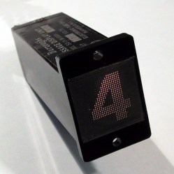
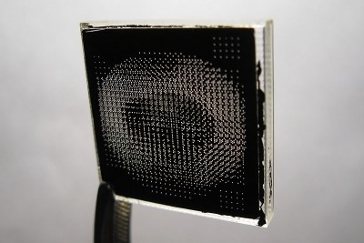
 Ever heard of a sphericular display? [AnubisTTP] laid hands on a (damaged) Burroughs SD-11 Sphericular Display and tore down the unusual device to see what was inside. It’s a type of projection display with an array of bulbs at the back and a slab of plastic at the front, and the rest is empty space. The usual expected lenses and slides are missing… or are they? It turns out that the thin display surface at the front of the unit is packed with a two- dimensional 30 x 30 array of small lenses, a shadow mask, and what can be thought of as a high-density pixel mask. The SD-11 was cemented together and clearly not intended to be disassembled, but [AnubisTTP] managed to cut things carefully apart in order to show exactly how these fascinating devices solved the problem of displaying digits 0-9 (with optional decimal points) on the single small screen without separate digit masks and lenses to bend the light paths around.
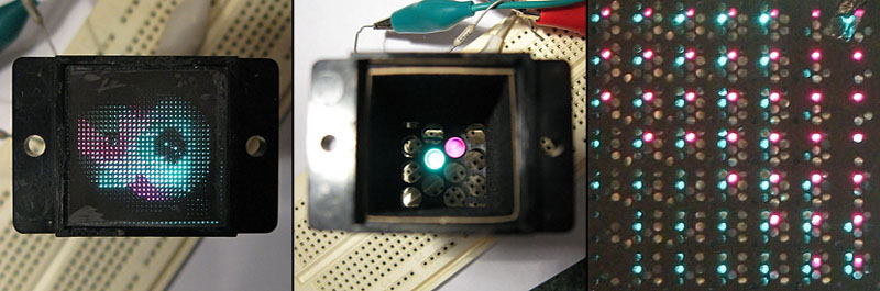
The face of the display can be thought of as a 30×30 array of pixels, with each of the microlenses in the lens array acting as one of these pixels. But these pixels are not individually addressable, they light up only in fixed patterns determined by the “pixel mask”. How exactly does this happen? With each microlens in the array showing a miniature of the bulb pattern at the rear of the display, a fixed image pattern can be shown at the front by putting a mask over each lens: if a certain bulb at the rear needs to result in a lit pixel at the front, that mask has a hole in that bulb’s location. If not, there is no hole and the light is blocked. Just as the compound lens is a two-dimensional array of microlenses, so is the light mask really a two-dimensional array of smaller masks: exactly one per microlens. In this way the “pixel mask” is how each bulb at the rear results in a fixed pattern (digits, in this case) projected at the front.
The Burroughs SD-11 Sphericular Display was very light, containing mostly empty space where other projection displays had lenses and light masks. It turns out that the SD-11 operates using the same principles as other projection displays, but by using a high-density light mask and a compound lens array it does so by an entirely different method. It’s a great peek into one of the different and fascinating ways problems got solved before modern display solutions became common.


Weren’t those used in PDP-7 computers?
Maybe for some customers. The PDP-7’s I had under care as a DEC field service guy didn’t have these. They had the usual (incandescent!) blinkenlights only.
It’s hard to understand the explanation on the HaD page, so click through to see more pictures. The key for how these works is “The angle of the light striking the refractor controls which digit is displayed,”
This is such a super interesting and clever design. I love this sort of thing.
It’s quite novel, all right, but I don’t see that it has any advantages over the IEE units that had the lenses at the back. Probably invented this just to avoid paying patent royalties.
The benefit was much reduced weight and half the size.
When were these things first marketed? A quick search on line reveals no dates at all.
I have an ad for one of these from 1966, which would be right in the sweet spot for weird number displays… transistors were readily available and created a need for cheap readouts, but LED displays were still several years away from being invented.
Also, transistors of the time were okay for turning on 28 V incandescent bulbs, not so much for 170 V neon displays. I think that these were quite a bit more expensive than Nixies, but it may have been a push once you considered the cost of drive electronics.
I mentioned this in the HAD article on the IEE projection display.
The patent (https://www.google.com/patents/US2981140) is somewhat helpful in explaining this. But also, think of this as an insect eye. Each “pixel” in the display has its own lens, and the lens transmits a value for that pixel that’s based on the angle the light hits that lens from. Or simplify this further and use a pinhole for each pixel rather than a lens. In this case, if you draw a ray from any of the lamps through a given pinhole, it will go through a specific (and very small) area of the film. That point on the film contains the information for that pixel. The lens just makes it a lot more efficient.
This seems to beg a bit of tinkering with 3D printed masks (likely on a bigger scale) just for the fooling-around-with-it value. If I ever get the spare time…
It might be trickier to print than the digital sundial (https://www.thingiverse.com/thing:1068443) owing to the requirement of lenses rather than just slots. I’ve tried printing with clear ABS filament and the results were anything but clear, even after sanding with wet and dry and water, and buffing afterwards.
Perhaps making a lens surface mould and then pouring or painting a clear platic solution on layer by layer could have better results.
You’re probably right. By coincidence, I was just looking at that sundial print yesterday!
Why not start with plain old 2d printing on transparencies?
Yeah, that could definitely be done. Each display pixel needs at least ten pixels (call it 4×3, but then you need a little margin, so probably realistically 6×5, and there are 30×30 pixels, so we’re only talking 180×150 pixels on the “character ROM mask”. Definitely doable on inkjet or laser printers. The tough part is still making the lens array (or more to the point, the mold for the lens array), but these don’t need to be as precise as the type used in the projection displays.
Let me see if I got this right.
Each microlens focuses the image of the bulb array onto a thin opaque mask to concentrate the light onto a tiny dot.
The position of the dot depends on which bulb is lit.
The mask has holes punched in such that for each displayed digit, the hole is placed in the corresponding spot for the right bulb. This makes the mask an optical OR gate.
As the light passes through the hole, the image of the bulb goes out of focus and the light spreads out again to illuminate the front mask evenly.
I think so. Presumably the placement of the front plate needs to be pretty accurate.
Hm. Thought I already answered this. Yes, that’s right. Your explanation is better than mine, so thanks.
Not sure about the OR gate, but maybe I’m just fuzzy.
With this display tech, it’s all about the angles. Light coming from different bulbs, passing through any given lens, will be at a different angle, which means that you know where the spots from the different bulbs will hit the mask. Put holes in the right place, and you’re done.
Makes me think: with something close enough to a point light source, you could just have the grid and the mask, and do away with the lenses entirely. Wonder if this is doable with LEDs… It might get large, but that just makes building it easier. (As someone pointed out above, this is the digital sundial, but with an LED in place of the sun.)
Thinking of it as an optical OR gate is a simpler way of thinking about the mechanism.
There’s a matrix of bulbs at the back. The microlens copies this matrix onto each “pixel” of the display as a camera would.
Each digit shares pixels, so each of the pixels must perform an OR operation. “This bulb is lit OR that bulb is lit OR that bulb…”
The rest of the display is merely about diffusing the light evenly after it passes through the gate.
The process of creating the mask for each digit is very simple. You put in film instead of the mask and place a second mask in the shape of the digit in front of the microlens array. Turn on the corresponding bulb, and that exposes the film with the correct dot pattern. Swap the mask for a different digit, turn on the other bulb, and another set of dots is exposed on the film etc. etc. Then you develop the film, make a negative copy of it onto a transparent medium, and there’s your dot mask.
The basic operation of the shadow mask in a CRT TV works by exactly the same principle. You may think of it as rays and angles, but it’s really a rudimentary pinhole camera that projects the image of the electron gun assembly onto the phosphors at the front.
That’s also how they get the different colored phosphors to align with the electron guns. The shadow mask is placed inside the tube, a UV hardening resin containing the correct phosphor is poured in under the mask, and a UV light source is placed where the corresponding electron gun would be. Exposing the resin through the shadow mask hardens the resin at the correct places on the inside of the glass, and then the excess resin is washed away.
The SD-11 display could use the same principle, replacing the microlens array with a simpler pinhole mask, but it would block 90% of the light from reaching the front, or result in loss of contrast, so a microlens array is used for efficiency, to concentrate the light through the tiny holes in the mask. This is the reason why CRTs use hundreds of Watts of power – most of the current is wasted on the electron beam hitting the shadow mask instead of flying through to the phosphors.
Reference: http://www.madehow.com/Volume-2/Cathode-Ray-Tube.html
Thinking of how you could reasonably reproduce the same system, you’d need a similiar assembly/grid of LEDs, a pinhole mask, a thin translucent plate, such as baking paper or a piece of a CD case brushed up with fine sandpaper, and a digital camera. You shine light through, photograph the resulting patterns, edit it up on the computer to mask the correct dots, and then print it onto a transparency sheet on a laser printer.
@Dax: Perhaps the first delta-pixel tubes were made like you describe, but first I see the process as way too complicated for mass production. In the normal tubes you have phosphor stripes and a hole mask. This can not be made thee way you described, the holes from the mask would form individual dots instead of continuous stripes and the phosphor stripes in TV CRTs have a very regular pattern.
In a Sony Trinitron tube you had a vertical wire-grid like mask so theoretical you could have exposed the stripes. But I am sure the components were just made to the required tolerances and assembled. And then the color purity was adjusted by a set of magnets.
Elliot Williams: the main function of the lenses in this application is efficiency. Simplifying this with the filaments as point sources, without the lenses, only the light that comes from the cone defined by a filament at its vertex and the circle that is the aperture of the mask. Add a lens, and that aperture becomes at least 16 times the area, so it captures more of the light from each filament.
Where to souce quired tiny lenses to make my own?
Also a troublesome part I think would be what the teardown calls the “pixel mask” which is a high density pattern of small holes in an otherwise opaque material. This would be an interesting items to re-create, it wouldn’t be easy.
Not difficult to make the hole mask. Two immediate options: 1) CNC mill, 2) chem milling using photoresist on a thin metal mask. These are both well within the hobbyist toolbox. For a 25 mm tall display, if there are 30 pixels, and the mask is a 4×3 array, that’s 120 pixels, for 25/120 = 0.2 mm. This is not that difficult. And if it is, you can go with a larger display. The lens array is still the hard part. If you try to use just a pinhole, the display will be VERY inefficient and dim.
Looks like we might be able to repurpose LED street lighting lens arrays for something affordable
The hard part is computing where the holes in the mask should go, because the pattern of the dots shifts depending on the distance of both the bulb and the pixel from the center of the screen. Each tiny lens or pinhole “sees” the bulb array at the back from a slightly different angle.
Dax – not difficult at all. The math just uses the principle of similar triangles. If the LEDs are 10 times as far from the imaging mask (the one that’s either a lens array or one pinhole for each “pixel”, then the spacing for the “ROM” mask is 1/10th the LED spacing. If you’re not comfortable doing the math, you can use a CAD program like QCAD or LibreCAD to draw the rays and get the appropriate positions.
Tedious, maybe, but not difficult. Once you measure the positions of a few points, the pattern becomes clear.
It is nice to see that the technology behind the light-field-camera or plenoptic camera is not new. :-)
By no means new. The idea originates in proffesor Lippman work in 1908 (integral photography). Various sorts of lenticular display media were with us in over past 60 years as well. The names of lumigraph and lightfield were given to this principle later on in 90s computer graphics research (Levoy et al.).
I’m currently building a clock using six Burroughs SD12’s. The 28v incandescent bulbs have been replaced with leds. The parent equipment was a Digital Readout System Model CRS-11HSB made by Infotronics in Houston and featured a 10 digit display and dates from the mid 1960’s.