
Before Lunar New Year, I had ordered two 3000 F, 2.7 V supercapacitors from China for about $4 each. I don’t actually remember why, but they arrived (unexpectedly) just before the holiday.
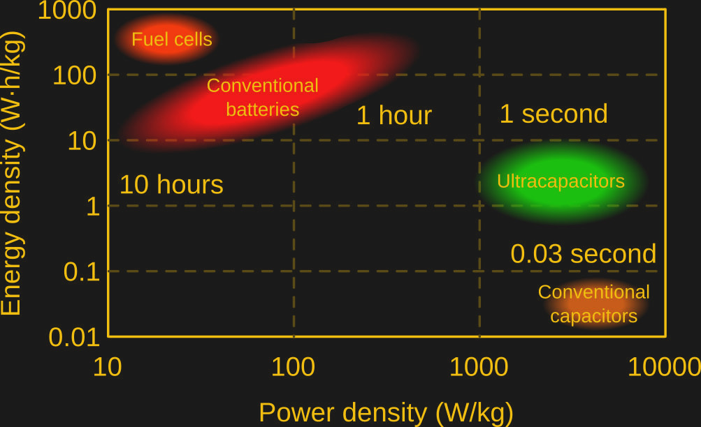
Supercapacitors (often called ultracapacitors) fill a niche somewhere between rechargeable lithium cells and ordinary capacitors. Ordinary capacitors have a low energy density, but a high power density: they can store and release energy very quickly. Lithium cells store a lot of energy, but charge and discharge at a comparatively low rate. By weight, supercapacitors store on the order of ten times less energy than lithium cells, and can deliver something like ten times lower power than capacitors.
Overall they’re an odd technology. Despite enthusiastic news coverage, they are a poor replacement for batteries or capacitors, but their long lifespan and moderate energy and power density make them suitable for some neat applications in their own right. Notably, they’re used in energy harvesting, regenerative braking, to extend the life of or replace automotive lead-acid batteries, and to retain data in some types of memory. You’re not likely to power your laptop with supercapacitors.
Anyway, I had a week-long holiday, and two large capacitors of dubious origin. Sometimes we live in the best of all possible worlds.
Each capacitor is allegedly capable of storing about eleven kilojoules, and delivering that energy at a frankly alarming rate. Exactly what rate is unclear, as I don’t have any documentation for the internal resistance, thermal tolerance, or even the polarity.
Further complicating matters is that all my suppliers are closed for the next two weeks or so. Whatever I was going to build, the first challenge was that it had to be built from the parts on hand. Second, most hospitals are running at reduced capacity right now – so even more than usual, it had to be reasonably safe.
For that and other reasons, directed energy weapons were out of the question. (Use science for peace please!) I did really need a spot welder though, and there was no shortage of examples of people who had built their own from supercapacitors, typically in the 500 F range.
However, I’m using six times that capacity, and I didn’t feel the safety precautions used in these builds (most often none) scaled particularly well. My concerns were in two main areas: a safe and efficient charging method, and preventing unintentional discharge.
The latter was simple to fix. As the supercapacitors were roughly the shape of a large battery, I put a collar around one electrode as a spacer. The tape is not structural, it’s just to hold the plastic in place for a photo and while inserting the capacitor.
Then I made a large version of an AA battery holder out of a weatherproof plastic box and some 0.7 mm thick copper plates I had left over from other projects. Later on, I’ll drill holes in these plates and attach thick copper wires with bolts. I may also pack the empty space inside the enclosure with something fireproof, like packed sand.
The capacitor fit firmly in place and I wasn’t able to dislodge it by shaking the case vigorously. The next challenge was to determine capacitor polarity so I could clearly mark it on the case. Out of habit, I pulled out a multimeter and measured the voltage across the terminals, without realizing that probably wouldn’t work.
Unfortunately, it did work. Someone has decided to ship the supercapacitor containing significant charge (about one volt). They were pretty well packed when I received them, but I still can’t imagine any reason they would ship them bearing charge. If any of our readers can think of one, please let us know in the comments!
Charge!
In any case, now that I could store and connect things to the capacitor more or less safely, it was time to build a charger. Certainly, there are many examples on YouTube of people manually connecting and disconnecting a lithium cell and current limiting resistor to the battery while also holding a multimeter in place, or connecting a large variable-voltage power supply with current limiting function. There are also voltage limiting and cell balancing supercapacitor protection boards that are a very reasonable option, but my suppliers don’t carry them and are closed for the next 2 weeks.
Directly using a battery was out of the question. A current limiting resistor wastes a lot of power, and human error can lead to overcharging the capacitor or polarity errors, reducing its lifespan (and possibly mine as well). The fail state of large capacitors seems to vary between ‘large firecracker’ and ‘small hand grenade’, both of which I prefer less. A high current benchtop power supply wouldn’t be great either, because it requires a wall outlet, and I was hoping to make this a mobile unit.
I had a few DC – DC buck converters lying around that were rated to 5 A of current. These are fairly efficient, around 85%, and can output down to 0.8 V with a DC input between around 5-32 V. My intended power supplies for this are a bunch of lithium batteries at different voltages, a 40 W 18 V solar panel, and possibly other things like old laptop power supplies.
I tore apart one of the broken DC – DC converters to see what chip it used. It was an XL4005E1 (PDF). The datasheet said that it has a ‘maximum duty cycle of 100%’ (hilarious for reasons we’ll discuss later) and had an active high enable pin. This seemed like a good way to limit the output current of the power supply to within a safe current using pulse width modulation.
While a 555 timer would have been sufficient, I used an ESP8266 because I plan to expand functionality later. The capacitor charge rate slows as it charges, so the ideal PWM duty cycle depends on the present charge level. Later on, I want to use the onboard analog to digital converter on the ESP8266 to optimize the charge rate, display charge state using an LED or screen, and turn off the circuit automatically to save power when charged. For now, the only goal was to find a reasonable duty cycle to charge the supercapacitor to over 2 V for testing. To this end I set the output to 2.5 V and connected the PWM output from the ESP8266 to the XL4005E1 enable pin. The PWM output was determined by the following simple program on the ESP8266:
pwm.setup(1, 1000, 650)
pwm.start(1)
Unfortunately, this didn’t work at all. The XL4005E1 always stayed on, and thankfully it shut down before any combustion occurred. Tying the enable pin to ground or VCC also had no effect – I suspect a counterfeit chip. Ironically, the datasheet was still exactly correct to say it has a ‘maximum 100% duty cycle’, it just turns out this is also the minimum duty cycle!
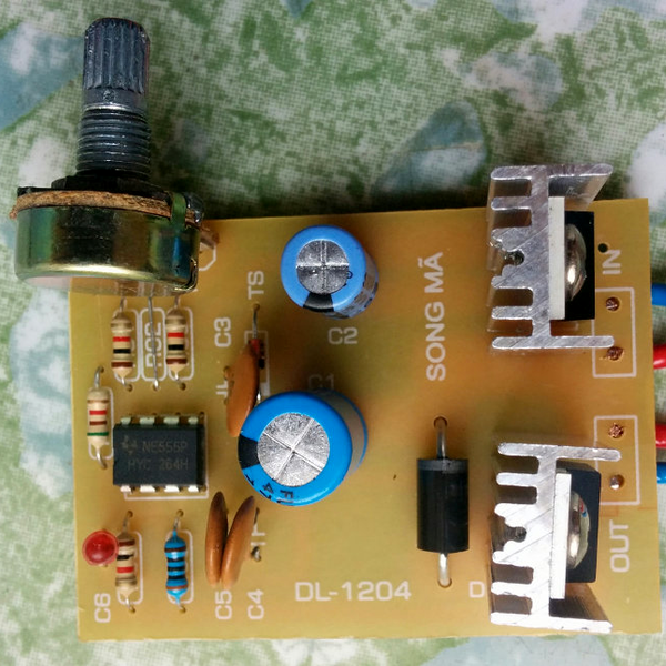
I looked around for something that could switch enough current to be a useful alternative. I found a stack of LED dimmers that someone had asked me to buy for them, and never picked up. They were super cheap, and I’m happy I kept them now. Inside I recognized a 9 V voltage regulator, a 555 timer, and an IRF530N power MOSFET (PDF) with heatsink.
I couldn’t help but think that if I just removed the 9 V voltage regulator, I could use the dimmer directly to control the output current of the power supply. However, that would mean no automated control later, and a dial without any particularly useful markings.
I desoldered the MOSFET, and used the 3.3 V output to drive the gate. The datasheet suggested this probably wouldn’t work, and frankly I shouldn’t have bothered. What did eventually work was connecting the input of the DC-DC regulator — it will always be 7.4-18V for my use cases — to the MOSFET gate via a 2N2222 transistor. The base of the transistor is connected to the ESP8266 PWM output. The PWM output allows the transistor to switch the DC-DC regulator input, driving the power MOSFET effectively.
I had found earlier that the DC-DC converter shut down if you draw more than 8 A. Through trial and error, I found a 40% duty cycle worked acceptably well while safely accounting for vendor optimism. The downside is that with a fixed duty cycle, the charge rate drops to nearly nothing when the capacitor hits about 2.15 V. My goal for testing was to charge it to 2 V, so this was acceptable for now. For convenience, I attached a small LCD voltmeter to monitor charge, and called it good enough for now.
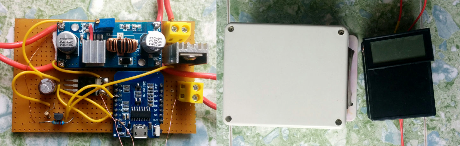
Admittedly, after a few unplanned revisions to the circuit this became a bit of a kludge of parts. If I had to redo this, I might keep the power MOSFET controlled by a BJT, but replace the ESP8266 with an 8-bit Atmel MCU. It would be smaller, more power efficient, a little cheaper, and I used to love programming those chips in ASM. Another big advantage of that approach is I can use pulse sequencing to add multiple power supplies in parallel, whereas that might not be practical on the ESP8266. Normally this would be unsafe – among other things one power supply failing means things get out of hand rather quickly for the others. However, if each power supply is connected to the supercapacitor via its own power MOSFET, and a microcontroller manages them so that only one is on at a time, it should be fine and offer a faster charge rate at an acceptable cost.
The next steps are to build electrodes and a high-current switch, then try welding different materials. I also want to optimize the charging circuit. I think this has been enough for one day, so stay tuned for sparks coming up soon.
UPDATE: Read the conclusion of this solar spot-welder adventure.


Brilliant artwork Joe Kim!
It is, but wrong (welding) process, though.
Anyhow, I’ve been meaning to build a spot welder for welding battery tabs, may be I’ll look into this one.
“but I still can’t imagine any reason they would ship them bearing charge. If any of our readers can think of one, please let us know in the comments!”
We used to wire (i.e. short) the terminals of our High Voltage capacitors (~20Kv?) when they were out of circuit, as they would develop a charge over time and surprise the next person who would handle it if the terminals weren’t shorted.
Seems like I recall someone noting online a conspiracy that the “arc of the covenant” was actually an air, like ambient conditions I guess worse in the desert, charged capacitor.
Hm. You could maybe do it with one terminal earthed, the other attached to some sort of collector. The collector would get charged from desert sand, or just air molecules, brushing past it. Might work! Lots of useful work was done with Leyden jars, which could’ve been built long back in history. You’d have to use clay instead of glass maybe, but still, “2 plates” isn’t a demanding thing to build for an ancient desert prankster.
https://en.wikipedia.org/wiki/Dielectric_absorption
(and you thought ferromagnetic materials were a stubborn bunch of hysteresics)
Thanks, I’d forgotten the term or physics behind it.
Double layer capacitors like supercapacitors usually work by having a molecular layer of ions on the surface of the electrodes act as the insulating barrier. If the capacitor is fully discharged for a long period of time, the barrier dissolves away and the electrodes may also start to dissolve.
In any case, these are symmetrical devices, and the polarity of the capacitor is determined by which way it was charged up the first time – by the formation of the insulating layer. Switching the polarity is possible, but the flip in polarity causes a galvanic reaction between the electrodes that damages the surfaces.
Another effect is Pseudocapacitance, which is employed in ultracapacitors as it can be 100x stronger. Basically, the capacitor works like a battery, with ions intercalating within a special sponge-like electrode, but there’s no chemical bonds so it’s not a true galvanic battery.
They’re also symmetrical devices, and also employ the double layer structure, the polarity being set at the factory by the first charge-up. If completely discharged, or the charge is being reversed, the double layer dissolves away and the ions may form chemical bonds with the electrodes, which results in reduced capacity as those ions are no longer available for use.
I don’t understand most of the concerns in this article. I’ve used 3000 F Maxwell caps, which I believe are actually 3000 F. I doubt a $4 Chinese one is actually that high. To charge them, it’s easy just to hook them to a power supply set to the voltage you want. Their short circuit current is like 19 A, so there’s no real concern of the power supply taking them over current. The only time I had to be careful was in voltage balancing two supercaps in series, and I just used the quick and dirty shunt resistor method to do that.
While you didn’t make any accusation here, I want to take a moment to be clear it’s not a concern about where it’s from (China), I’m concerned because it looks like it didn’t meet quality control standards, so didn’t have a label applied, and was then sold ‘grey market’ and made it’s way into normal circulation. Most of my parts and tools are from China and the quality is great. I just wanted to take a moment to appreciate that :)
That being said, I too have serious doubts about its actual capacity and internal resistance, but we’ll see how it goes. All I know now is that it charges to 2.6 volts without anything terrible happening.
To be honest, my biggest concern with that capacitor is it’s really easy to short it out. The end where I put the plastic collar doesn’t stick out as much as it looks like it does in the photo. If you just press it against a piece of metal it will likely short out (without the collar).
OK, well that and working with a fairly high power part with no datasheet, in a country where I barely speak the language, during a time when the hospitals are barely open. Maybe I did overdo it a little though.
Please explain the quick and dirty shunt resistor method.
“‘maximum duty cycle of 100%’”
I was looking at a Horror Fright stud welder the other day,
https://www.harborfreight.com/stud-welder-dent-repair-kit-61433.html
and its Duty Cycle is 2%, the box says only one stud can be welded every 8 minutes!
They must using a different type when I watch the Velocity Channel where they sequentially weld the studs seconds apart.
B^)
Was wondering yesterday if those copper looking studs were actually copper so could use for hacking together a heat sink. Online looks like they’re steel with a copper coating of some sort. Wound up picking up a $49 with coupon 2500lb winch that I need to make a block with a Threefold purchase tackle I think is the term.
IMO, a plain copper rivet wouldn’t stand up to the force of the dent puller, but it would need copper to make a good electrical contact.
Right. I was thinking the same… though have had this copper nail heat sink design in my head that I just noticed is on the market by Enzotech. So, I see copper and that is my one track mind first thought.
I think this started from reading years ago an article I’m not finding online or saved regarding a radio operator who made his whole system using this style method that I found hackaday has referenced, though using copper nails and I think copper flashing to shield sections of his circuits: https://hackaday.com/2011/04/06/circuit-building-with-a-hammer-and-nails/
I’m going to buy a box of copper nails now since I need a capacitor discharge tool and seems like a great justification to get the ball rolling on these thoughts being applied.
I’d just build a small constant voltage charger using an LM317 and a pass transistor or two if I ever felt the need to build a dedicated circuit to charge my supercaps. I don’t, so I’ve been able to use a variable power supply set to 2.5V (and my Fluke meter for verification) to charge mine. Never had any trouble doing it this way.
Wow, so allegedly 10,000 Watts in a second. Neat, great timing. Was watching discharging capacitor devices on youtube.
So for say like regenerative breaking… the generator charges the capacitor at a high rate like you’re trying to determine optimally… more-so a limit fault protection needs to be integrated. Then in the circuit design to discharge in a PWM slower way to charge a battery with the super capacitors stored energy in between braking cycles.
Wondering how these can be retro-fitted to my 2001 Dodge Ram for use when braking. Coil or magnets balanced on my drive shaft?
You would need a 900kJ capacitor bank to handle stopping from 65mph if my math is right.
Roughly 90 times the volume of the one 11kJ supercapacitor? Doesn’t seem unreasonable. Mass energy balance along with duty cycle to time feasibility of discharge rates into the batteries I’m guessing unless there is some more circuitry to use directly with motor use and not charge batteries only when ICE is used?
Watts are joules per second. Watts per second would be, uhm, the rate at which power is used? Like maybe “The power increased by 10 Watts every second.”
Watts per second would be a unit of power slew, or essentially how quickly something could react to a change in demand or control input.
You see volts per second quite commonly in amplifiers and gate drivers, and amps per second on some FETs I think. You could conceivably use watts per second to measure response time of an engine or anything that is slow to develop or drop off power.
He might have meant “10,000W for one second”.
Yes, Greenaum: “a” = “1”
My thoughts are they discharge in “a” second also. Therefore, I’m not sure the optimal charge rate to utilize capacity for the typical braking speed and I’m not sure of the optimal discharge rate that is the optimal charge rate for the battery I was envisioning to discharge the supercapacitor power into. Thinking from the perspective to not waste heat or energy from typical mechanical (albeit with hydraulic braking) operations that do.
Back at Tech and I think more around the early 2000’s I was advocating and investing in lithium companies to drive the market demand. Interesting was barium titinate and some other more common lower cost materials than lithium seemed feasible for use as supercapacitor material… though obviously (if you lived around a methville) with all the illicit lithium uses… lithium had some other market impetus.
Even then, I saw the area of opportunity to have a supercapacitor bank buffered in between the regenerative braking and charging process to help save and use more energy that at the time since lithium ion batteries weren’t implemented en mass can be even more potentially value added.
It’s “in” vs “for” that was the confusion. When speaking of time, “in” usually means “that much time, or quicker”, “for” is more used for duration.
As far as your plan, if you’re going to use it for braking, it has to have enough strength to actually brake the thing. A coil or magnets sounds a bit wimpy and half-arsed. You’d need a generator, ideally one that can do really high capacity for short periods. Obviously looking into F1 racing would be an option. In electric cars, they use the existing motors, which are already huge because they’re the source of propulsion. Would be expensive and bulky just for braking.
And then when you’ve got the energy, what would you do with it? You could charge the main battery, take the alternator’s load off the engine. But the alternator doesn’t take a huge amount of power / energy from the engine. For the large expense and bother, you wouldn’t be saving much. Regenerative braking makes sense on EVs cos of the limited range a battery has. Regeneration can scavenge up useful amounts of energy, though if the motors weren’t in place anyway, I dunno if they’d bother putting a system in just to do that.
I think it only makes sense in electric drive vehicles. Or in F1 where every tiny little advantage is worth spending millions on, til they ban it.
You could save fuel if you could use the electricity to drive the wheels, but that’s an even bigger kettle of fish.
I see what you mean in regards to my wording. Makes sense, if “for” is more appropriate, I’ll take your word.
For some reason in regards to retro-fitting I was thinking using the drive shaft since is already there wasting energy in the mechanical operation and is a rotor where adding magnets wouldn’t hurt storing energy in either acceleration or deceleration. Some sort of coil design would have to be added most likely able to articulate with the drive shaft. Maybe is something better at each end of the shaft so to mount on the axle or transmission to reduce complication. I was just brainstorming.
Technically, what can be more efficient is having a higher quality engineered electric hub system that can be retro-fitted. That would be the only other way I can think of getting away from more mechanical drag other than maybe inline between the engine and transmission. I think most are too lazy and patent rights and claims might cause issues for amotivation.
I’m not sure the mass energy balance benefit with faster charging batteries and losses when breaking where supercapacitors can store the energy and there prevent loss. Might be interesting for someone to calculate out to see if there is a market.
Like you noted… rally and the European race car market is where I recall some of the first supercapacitor hybrid race car designs that did use lithium something batteries. I forget. Seems the slower charging batteries would benefit and maybe the slower discharge batteries also for starting off acceleration.
FYI: Supercaps are bipolar. Also, I use a dc-dc converter with current limiting feature to charge my caps. Produces constant current charge until close to fully charged.
Bi-polar eh?
Maybe they should take lithium, I heard that can help.
B^)
Eh, rumor has it charging them from lithium cells should cover it!
Possibly just be a placebo affect through.
There are such things as lithium ion supercapacitors.
Curious about this, I went to the parts bin for a supercap that had a label. It definitely had polarity markings indicated. If the markings are indeed irrelevant, I’d be interested in knowing why! Do you have a reference?
A DC-DC converter with a current limiting feature is an excellent and straightforward idea. Unfortunately my particular model limits to 8A and the maximum it can sustain without combustion is 5A (and even then it gets very hot). I would certainly choose a different model next time.
Supercaps are definitely not unpolarised, if that’s what you meant by “bipolar”. Some people claim they can be charged in the wrong direction, but you’re not supposed to, and it will damage the cap.
Bipolar supercaps are a different thing altogether, and are a way of squeezing 2 or more effective caps into the body of one, for higher voltage rating.
Supercapacitors are symmetric devices, but not bipolar. The polarity is set by the first charge, which forms the insulating double layers against the electrodes.
Reversing the charge temporarily breaks up the insulating barrier, and the capacitor acts like a galvanic cell until the reversed barrier is formed, and during that time it’s basically shorted out and cooking itself. This is why you can’t put electrolytics, supercapacitors etc. in an AC circuit.
That’s actually what I meant. Should have been more clear about it…
They are charged with a very low current in the factory to polarize the capacitor. This forms the barrier that makes it act like a capacitor. You can charge one with the wrong polarity, as long as you do it very slowly. The barrier will break down and then slowly reform the other way around. Now you have a mislabeled capacitor…
From the second paragraph:
Huh? One of those “density”s must be incorrect, right?
No, capacitors store very little power per unit mass or volume, but they can dump it out really fast
Is it even practical to discuss “power per unit volume” of capacitors since it’s inherently variable? Even using the same capacitor bank. Capacitor composition aside you’re more likely to be limited by the switching hardware or device consumption limits, assuming you’re not using it to make big sparks.
By variable do you mean according to the voltage it’s charged to? In this case, since it’s supercaps, the maximum voltage they can tolerate is very low. Usually you’d charge them to the working maximum, since they’re so expensive you wouldn’t waste the capacity. So the voltage they’ll be charged to is usually the same, whoever uses them.
No I mean variable in that using the same capacitor in 3 different circuits will get you 3 different power outputs. This only seems relevant when you’re discussing which capacitor construction to use.
It’s like talking about the 1/4 mile time for a specific engine while completely ignoring the car weight, transmission model, fuel mix, driver, etc.
Without knowledge of the circuit you’re putting these capacitors into it’s not terribly helpful to say ‘this capacitor is capable of 10 PW output” if you’re a crap designer and your circuit is only capable of drawing / switching at 10 W.
But I don’t design circuits for a living, so what do I know.
Well it’s the maximum output. All components have ratings and capacities, the resistance of a resistor doesn’t vary with it’s use, even if the voltage across it does. What other sort of output would you measure? Without a measurement like that, you wouldn’t be able to tell which cap is bigger than another. Comparing like with like, in this case standing alone, is how it’s done.
Your point’s a bit confusing, do you mean what I think you mean?
It makes perfect sense to compare the energy density.
Running with your car analogy here, a given cap woul be equivalent to an engine, and its power output would be the engine’s horsepower rating.
You’re saying that depending on the circuit, you’d get different amounts of power out. That’s true, but likewise you’d get different performance from putting the same engine into different vehicles.
Also, you may purposely not use the cap to its max, just as you are unlikely to use 100% of your car’s HP at any given time.
The MAXIMUM output of the cap, just like an engine’s HP rating, doesn’t change because of the application it was used for.
Yeah, I’m like… the units are “kg” and I’m used to density being “kg/m^3.” So like examples noted seem to describe and I though with more details regarding materials made from and maybe design style even would be a cool presentation. Like, I want to place a 1.8L CVT hybrid drivetrain in my 2001 Dodge Ram. Volume is a constant though might benefit from ultra/super-capacitor energy/power on acceleration more compared to the Prius. Say with same battery and cap bank. Then there is the financing bank… wait… that’s a different variable that is a limiting factor in the equation and may not be considered a co-efficient of performance or capabilities. Would look cool on a graph and presentation.
I stumbled when reading that too, until I noticed that one was ENERGY density and the other was POWER density. Those terms have the same meaning in conversational english, but are very different in physics or electronics.
I would really like to know where you got even a “fake” 3000F 2.7V capacitor for $4. I have been looking for some for quite some time, the typically go for $30+ even on fleabay.
I’ll sell you one for $3. The packaging may claim to be 47uF, but that’s just cos they’re fake.
Man, I want to see a graph of the specific designs of energy storage devices (say batteries between capacitors) in relationship to the materials used in the devices with the same energy density and power density x and Y axis. I wonder if a Z-axis relating volume or other metric would be interesting. That would be and awesome poster especially if it had a bunch of graphics with dimensions of qualitative or quantitative information.
I’m still jaw dropped shocked at “I had ordered two 3000 F, 2.7 V supercapacitors from China for about $4”. $4?!?!?
The cheapest I’ve been about to find a 3000F supercap, used, is more in the vicinity of $40 bucks than $4. Could he have meant 300F??