Many of us will have seen the portable solar panels offered on our favourite online purveyors of electronics, but some who have bought them remain unimpressed with their performance. [t.oster92] had just such an issue, and concluded that since it had great dull-day performance, it wasn’t the panels themselves that were at fault. There followed a teardown and an investigation of the circuitry inside.
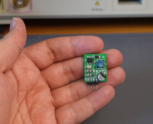
The panels fed a small PCB containing a buck converter, with an 8-pin SOIC carrying an untraceable part number. Some detective work revealed it was likely to be a rebadged version of a more common part, which exposed the problem as a converter without the rating to deliver the power it should. The solution, at least in part, was to replace it with a more powerful chip on a module and reap the benefits.
This would be the end of the story, but this is an ongoing project. Next up will be adding MPPT capability to extract the last bit of juice from those panels. That makes this one a story to keep an eye on, because we could all use a decent set of panels.
This hack is part of our 2026 Green Powered Challenge.


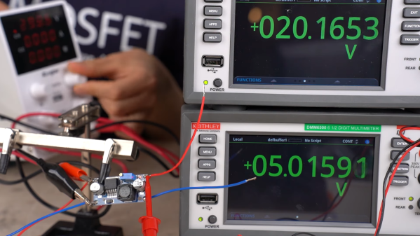
 Or do you? It’s not so clear after watching [Denki Otaku]’s video on a bargain bag of buck converters he got from Amazon — ¥1,290 for a lot of ten, or $0.85 a piece. The thing that got [Denki]’s Spidey senses tingling is the chip around which these boards were built: the LM2596. These aren’t especially cheap chips; Mouser lists them for about $5.00 each in a reel of 500.