You’ve written your firmware code, etched your own PCB, and now it’s time to put that awesome new project of yours into an enclosure. Unfortunately, all you have is a generic Radio Shack project box that you picked up when they were clearing out their inventory. If you put your project in that, it’ll have all the style and grace of a kid wearing hand-me-down clothes. Your project deserves a tailor-made enclosure, but the prices and lead time on custom plastic enclosures are prohibitive for one-off projects.
In Ye Olde Olden Days, the next step might have been to start bending some sheet metal. But it’s the 21st century, and we’ve got mechanization on our side. The “Ultimate Box Maker” by [Heartman] is a fully parametric OpenSCAD design which allows you to generate professional looking enclosures by simply providing your desired dimensions and selecting from a few optional features. In a couple of hours, you’ll have a custom one-of-a-kind enclosure for your project for a few cents worth of filament.
That’s the idea, at least. For this edition of “Printed It”, I’ll be taking a look at the “Ultimate Box Maker” by generating and printing a basic enclosure. As somebody whose Radio Shack was out of enclosures by the time I got there and who doesn’t want to slice his hand open folding sheet metal, I’m very interested in seeing how well this design works.
Configuration
So in theory, this design is supposed to work with the Thingiverse Customizer, which is basically just a web front-end for OpenSCAD. You get nice little sliders and dialog boxes, and once you have all your information entered, it will render you a custom STL to download. It’s arguably one of the best ideas MakerBot has come up with in regards to how Thingiverse works. Unfortunately, at the time of this writing, Customizer doesn’t seem to work anymore and just gives an error about missing libCGAL.so.10. Sigh.
 In that case, we’ll need to download the .scad file from the “Thing Files” tab and open it up in OpenSCAD locally. All the configuration values are up at the top of the file and clearly labeled, which makes this fairly easy.
Obviously, you’re going to want to adjust the overall box dimension variables at the minimum. But there are also a whole set of options for PCB standoffs (position, diameter, screw size, etc), as well as options related to the built-in vents.
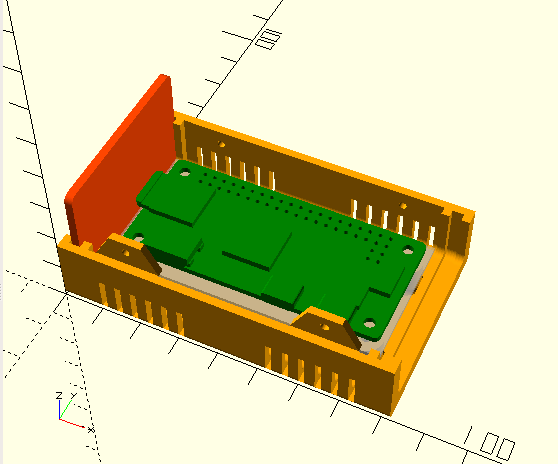
Making use of the OpenSCAD import(); function, you can bring in an STL of an existing PCB and see exactly how it will look in the rendered case. As a demonstration, I’ll be making a small enclosure for the Pi Zero, so I’ve imported an STL of it and used that to align the PCB standoffs. But even if you don’t import an STL to use as a guide, there’s a helpful “ghost PCB” that floats around inside the case while your editing the file in OpenSCAD.
Exporting the STL
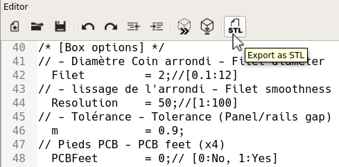
Once you’ve edited the variables to your liking, you’ll want to scroll a little farther down in the code to find a section that looks like the following:
/* [STL element to export] */
//Coque haut - Top shell
TShell = 0;// [0:No, 1:Yes]
//Coque bas- Bottom shell
BShell = 1;// [0:No, 1:Yes]
//Panneau avant - Front panel
FPanL = 0;// [0:No, 1:Yes]
//Panneau arrière - Back panel
BPanL = 0;// [0:No, 1:Yes]
These options selectively turn on and off the different parts of the model for when it comes time to export the STL. If you don’t turn the other parts off before export, you’ll just get a useless “assembled” STL.
 Unfortunately, the script is not smart enough to reposition the objects for STL export; so you’ll have to manually flip over the top piece in your slicer, for example. Another annoyance I found is that, even if you turn off the bottom of the case (BShell), the PCB feet still remain. You need to go back up to the script configuration settings and turn them off manually, look for the option called “PCBFeet”.
Having worked with OpenSCAD for a while I know why [Heartman] wouldn’t have included rotating the parts on export: it’s a whole lot of code to implement something that the end user can do with a click in their slicer. But making sure the PCB standoffs aren’t rendering when the user is just trying to get the top or side panel is a fairly big omission and would really only take a single conditional statement to fix.
Finally, there is some early support for generating customized front and rear panels, including functions to generate openings and labels. But personally, I would suggest just taking the blank panel generated by the OpenSCAD script and importing it into a 3D CAD program your comfortable with. The panel generation code just isn’t ready for prime-time, in my opinion.
Printing
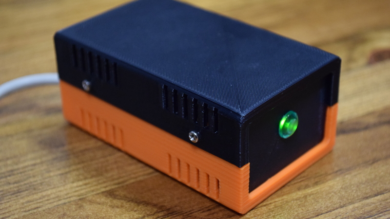
The design that [Heartman] has come up with for the case is really quite clever, and shouldn’t pose a problem printing. There are no overhangs so support is unnecessary, though you may want to turn off the vents if your printer has issues with stringing, as the thin openings can get clogged up. I printed my case at 0.2 mm layers and 15% infill, though larger cases could probably get away with 0.3 mm layer height for the sake of speed.


The design is forgiving in terms of tolerances, and no cleanup was needed after printing to get the parts together. The fit on the front and rear panels is perfect; loose enough that they don’t need to be sanded to git in the channels but tight enough that they don’t rattle around once the lid is screwed down. Incidentally, you must screw the lid down, as the two pieces don’t actually have any interlocking components. A potential improvement to the design would be a way to make the lid snap-fit.
Final Thoughts
Overall, I think the enclosures generated by the “Ultimate Box Maker” OpenSCAD script are fantastic. They look extremely professional, are very sturdy, and print easily. This is definitely a design I’ll be adding to my regular bag of tricks going forward.
I especially like that this is a printable design that clearly addresses a valid need. One-off projects need one-off enclosures, and 3D printing is perfect for that. While we’ve previously covered printed tools that deserve a spot on your bench, the argument could always be made that you’d be better off buying the “real thing”. But I believe this project offers a solution which is actually superior to traditional methods in a number of ways.
Thingiverse’s Customizer dropping the ball on this one is especially annoying, as [Heartman] went through the trouble of making sure his design worked with it — there’s some special syntax Thingiverse has you add to OpenSCAD to make their front-end work. Having a web-based tool to generate custom enclosures would be extremely handy, and I wonder if somebody in the community might just take up the challenge of restoring the service MakerBot seems not to maintain?


hi everyone, i want you to know i’m one of the snobs in this here comment section and i have to say:
openscad is easy. it’s easier to just make your own enclosure from scratch, especially if it’s as simple as this one.
You’re seriously going to try and say it would be easier/faster to write the code for a new enclosure than simply use this proven code somebody has gone through the trouble of putting out as open source? Come on…
+1^^
As a person who uses CAD every day for work, OpenScad just blows my mind. I don’t understand how anyone would be willing to use it. Bravo…I guess?
+1 here
Well, if you’ve ever needed to make almost exactly the same part many times, you would understand. Boxes are a perfect example, where you might want everything to be the same – wall thickness, edge radius, ventilation slot patterns – but in a different size. There are CAD programs that make this relatively easy, and I guess you could also write Python or C programs to generate STL files, but OpenSCAD includes all the nice 3D things like intersections and unions. Using OpenSCAD is a little like getting fed up with manually renaming a gazillion files using a GUI file explorer, and instead writing a program to do it for you. Doesn’t pay off if you only have a need for two or three custom boxes, but pays off over time.
In my youth I dabbled with POV-Ray.
OpenScad uses the same principles, so to me it’s easy to think in only few elements and think about the interections and differences.
Well, as a person who codes every day for work, OpenScad certainly is much much friendlier to me than a CAD behemoth with its scattered UI and gazillions of icons that make me cringe…
So much for every person’s point of view :-)
As a typical hackaday reader, I have one thing to say: A bunch of freaking paragraphs.
probably easy if you can code
Very cool. I’d countersink those screws for aesthetics.
It’s not a bad place to start and definitely a great effort. I’ve used it a couple of times and have had issues with the tabs that extend to hold the case together printing well (and holding everything tight), so I modded it to use heatset inserts and screws instead of the side tabs. It’s also a great learning tool if you’re just getting started with OpenSCAD (like I am).
It’s nice if you want to throw something quick together. I’d prefer my own design though, often with the minimum possible size in mind. I now also have a cnc router which is great for larger boxes. It’s often quicker to mill something out that’s large than to 3D print it. And the option of mixed materials like wood, acrylic and aluminium is also great.
I use a parametric solidworks model for milling boxes out on my cnc machine. I almost feel like i should turn around and make one from openSCAD for other people. I think the largest challenge is the work holding and that a single setup on a CNC machine is hard to design, Its not impossible but it creates limitations.
I’m not convinced snaping togetherness would be an improvement, it tends to lead to gouging the case to open it and/or not bothering with the screws later on.
I used this technique to open and customize the design in OpenSCAD:
https://www.youtube.com/watch?v=knKgMEod11U
YIKES!
Nice looking case. I like the two colors as well. In the past I would modify an existing case as opposed to a Hammond enclosure to get a “professional” look, but 3d printing is getting close (I’m talking hobbyist printers).
I know what you mean, best you could say about some is that they looked like they were very carefully glued together out of strands of spaghetti.
Has anybody had luck using this with http://www.rollapp.com/ ?
Customizer is working for me.
Are you actually seeing a preview of the STL? You have to scroll down to see the error message.
I get
/usr/local/bin/openscad/openscad: error while loading shared libraries: libCGAL.so.10: cannot open shared object file: No such file or directory
Thingiverse’s customizer hasn’t worked for me for months. However, OpenSCAD does have a version that is capable of customization locally. The most updated build has this disabled as of a few weeks ago, but if you download and install the development snapshot, and enable customizer it will enable you to customize the customizer-enabled files downloaded from thingiverse locally.
I’ve not really gotten into 3d printing, but this is the kind of thing that makes me think about getting one, could definitely be useful.
Too bad clicking open in customizer does not work. They say it may work if you download and install ope scad and some other piece to it, but they also said the customizer would work. It would be nice if HAD checked this stuff out first.
A 3d printed, custom designed, enclosure for it’s own electronics was one of the first things I designed/printed with my Tevo Tarantula – https://www.thingiverse.com/thing:2285617 – I’ve been hooked ever since :)
Got fed up with OpenSCAD for my enclosures, the code became unwieldy relatively fast, specially when starting to print in battery holders, moving on to OpenJSCAD https://openjscad.org/ was a relief
I don’t see how switching to javascript is an improvement.
Since you explicitly asked for it:
We actually build a web-based configuration tool to generate custom enclosures.
Yall experts feedback wouldn’t hurt ;)
https://coshape.io/sites/coshape/electronics_case_arduino/
1. It looks like the top is intended to be glued. Might be fine for some, but I would only use a box that can be easily reopened. So, screws should at least be an option.
2. I’m using Safari on an iPad at the moment, and the cutouts don’t change when a new selection is made on the Cutout menu.
3. I assume the Cutout menu just applies to the pattern on the top. If so, how do you specify cutouts in the sides? Maybe if the Cutout menu worked on my iPad this question would be answered.
Overall, it’s a great idea. I’d love to see something like this fleshed out, especially with options like heatset inserts for screws, countersunk or recessed screw holes, vents, and mounts for batteries. I know that’s asking a lot, but iterating, let alone fixing things in the slicer, is hard, if not impossible, for those of us who don’t own printers and get our prints from services like Shapeways
Hey Tom, thanks for the writeup. I checked it out, and I’ve made a ton of updates to the box, which I think fix some of the issues you had with it, as well as enable a few new cool features. I think you’ll like it. https://www.thingiverse.com/thing:2938921 and all the changes I made are logged at https://github.com/jbebel/Ultimate-Box-Maker
While I appreciate people developing things I might have a use for, and make them available free of charge, I’m afraid I can’t use your work because it is poisoned by the restrictive licensing it inherits from Ultimate-Box-Maker.
I do understand that people like to get credit for their work, but when they use COMPLETELY free – free as in beer, free as in speech – tools like OpenSCAD, and then put restrictions on their comparatively small investment, they just show how little they understand the concept of Free-and-Open-Source-Software. I’m afraid I’m going to have to develop my own parametric box system, just so there will be a free one available. This isn’t rocket science.
I have a parametric LCD case scad that I made for bending aluminum sheets (or even cardboard) into the size you need. You export the svg and print it full size then glue it to the aluminum/cardboard and bend at the lines. I recently made a RasPi case with a hole for a screen and while not 100% perfect, it certainly got the job done. I could clean that up a bit and release it as public domain. Then you can make all the cases you want, super free. I’ve been meaning to upload it to thingiverse. I’ll try to clean that up and then I’ll post here again when it’s done. Oh yeah, it’s not for 3D printing, but it could probably be adapted to 3D printing with just a few rotates and translates.
I should also point out that th Ultimate-Box-Maker is restricted to NO COMMERCIAL USE, so by not including this in your restrictions, you are violating the Share-Alike terms.
Forgetting to include non-commercial was an oversight which I fixed. I thought I used the same license as the original. It is indicated that way in github, as I kept the original license file. I can’t change the license since the original used that license. Is there a way to say my changes aren’t CC so you only have to give credit to Heartman? To be honest, I re-wrote almost every single line of code. It only resembles the original in functionality.
I’m no expert on this, but I was thinking about adding some extensions to the Ultimate-Box-Maker myself, and the fact that it had that clause stopped me. I also considered looking at his code and just doing the same thing a slightly different way, but this would be unethical and possibly illegal. I believe that the code for making parametric boxes is simple enough that I can do it myself without looking at any of Heartman’s code, and this would avoid any ethical conflict. Heartman certainly has no claim to the idea of a parametric project box. Since you acknowledge that your design is based on Heartman’s, this binds you to his restrictions. That’s my opinion. Now, if there’s really very little of his code left, and that code of his is not particularly unique or clever (i.e., it’s just what would be the obvious thing to do based on OpenSCAD’s capabilities), then it might be that what he makes claim to is just his own implementation, so it might be sufficient to purge your code of any vestiges of his, and then remove the “derived from” notice, but I think that would just invite a conflict.
I’m not sure why so many commenters are so concerned that Thingverse’s customizer doesn’t work. Have we become so dumbed-down by the AGUI (Almighty Graphical User Interface) that we are too frightened to change values at the top of a text file? It’s not like you need to see the box change as you drag a slider – if you need a box for a particular purpose, you type in the dimensions, whether it’s in a GUI wizard or at the top of a text file. What’s the big deal? I mean, how is it easier to type a number into a box labeled “Length” than it is to change the number in a line of text that says “Length = 160;”????
Oh, I see, you don’t want to be making changes to the master file. Well, there was an ancient trick used back in the age of dinosaurs and command lines: you make a copy of the master file, and edit THAT.
Here’s how The Ultimate Box Maker’s script (U_Box_V104_Test_Cleaned.scad) starts out, after a few lines of identifying itself and showing the convention used by the author for the order that points are specified:
/* [Box dimensions] */
// – Longueur – Length
Length = 160;
// – Largeur – Width
Width = 170;
// – Hauteur – Height
Height = 100;
// – Epaisseur – Wall thickness
Thick = 2;//[2:5]
/* [Box options] */
// – Diamètre Coin arrondi – Filet diameter
Filet = 2;//[0.1:12]
// – lissage de l’arrondi – Filet smoothness
Resolution = 50;//[1:100]
// – Tolérance – Tolerance (Panel/rails gap)
m = 0.9;
// Pieds PCB – PCB feet (x4)
PCBFeet = 1;// [0:No, 1:Yes]
// – Decorations to ventilation holes
Vent = 1;// [0:No, 1:Yes]
// – Decoration-Holes width (in mm)
Vent_width = 1.5;
Once you figure out that “//” means that everything from that to the end of the line is instructions or clarification for the user, rather than code, it’s hard to imagine anyone able to operate a 3D printer, who can’t figure out how to change the parameters in OpenSCAD’s editor.
I know I’m a bit late to the party, but I did the thing: https://lightningboxes.com/. I’d love to hear any feedback you might have to improve the designs or the site.