Love them or hate them, Nixies are here to stay. Their enduring appeal is due in no small part to the fact that they’re hardly plug-and-play; generating the high-voltage needed to drive the retro displays is part of their charm. But most Nixie power supplies seem to want 9 volts or more on the input side, which can make integrating them into the typical USB-powered microcontroller project difficult.
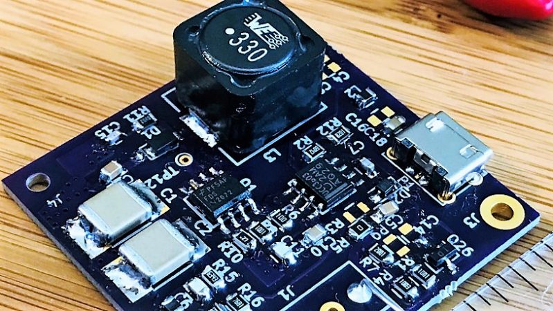
Fixing that problem is the idea behind [Mark Smith]’s 5-volt Nixie power supply. The overall goal is simple: 5 volts in, 170 volts out at 20 mA. But [Mark] paid special care to minimize the EMI output of the boost converter through careful design, and he managed to pack everything into a compact 14-cm² PCB. He subjected his initial design to a lot of careful experimentation to verify that he had met his design goals, and then embarked on a little tweaking mission in KiCad to trim the PCB’s footprint down by 27%. The three separate blog posts are well worth a read by anyone interested in learning about electronics design.
Now that [Mark] has his Nixie power supply, what will become of it? We can’t say for sure, but it’ll be a clock. It’s always a clock. Unless it’s a power meter or a speedometer.


I bought something like this on eBay. Search for ‘nixie 5v 170v’.
Note that the 5V input will draw about 750 mA at full power. So you can power it with a USB charger, but not a USB port.
Not unless you ask the port nicely first.
While according to the USB specification, you are not supposed to draw over 100mA from a port, motherboards in PCs typically have no actual control over current draw other than possibly a self-resetting polyfuse. Years ago I worked for one of the (at the time) big computer manufacturers and all our motherboards had the USB ports fused in pairs with a 1 amp polyfuse. So if you weren’t drawing anything from the other paired port you could suck 1A out all day long.
Of course, I meant to write “not suppsed to draw over 100ma from a port without asking the OS first.”
USB 3.0 is rated for at least 900mA. And that’s basically standard on every new PC.
I always wondered, why people are always using boost converters for Nixie tubes instead of flyback, forward or RCC topologies. Boost converters are suboptimal solution when there is big difference between Vin and Vout…
Transformers are tricky – but I do wonder how easy it would be to make a few hundred volts out of something small and cheap like a PA2718NL (just looking at the cheap options on digikey).
Using offline flybacks (such as the transformer you mentioned) can indeed work in reverse, but has higher leakage inductance because the secondary should be wound over the primary. These are somewhat ideal for winding your own though, as often the secondary has a sensible number of turns, making the AL value handy for say 100uH primary, requiring only ~20 turns. You just need to wind it yourself, with the primary layer first. And for 5-170V boost, anything from 1:5 to 1:10 turns ratio would do.
You are right, but you get chokes easily off the shelf, transformers not so much. And with a transformer you always have to deal with leakage inductance and stuff like that.
How is it different from a flyback converter
A flyback uses a coupled inductor – two windings on the same core, but still an inductor because it stores energy. Essentially it is a boost converter with a second winding for both isolation, and gain (the turns ratio determines the ratio of primary and secondary voltages). So, with a turns ratio of 1:5, and you use the primary as the boost converter inductor creating ~30V, the secondary reaches ~150V. This means the switch only has to deal with ~30V rather than 150V meaning you can use a MOSFET with a lower on resistance, increasing efficiency. This design is a boost converter, using just one inductor (more readily available) and has no isolation – the output is connected to the input via a diode and inductor.