
Last time, we covered storing and charging a 3000 Farad supercapacitor to build a solar-powered, portable spot welder. Since then, I’ve made some improvements to the charging circuit and gotten it running. To recap, the charger uses a DC-DC buck converter to convert a range of DC voltages down to 2.6 V. It can supply a maximum of 5 A though, and the supercapacitor will draw more than that if allowed to.
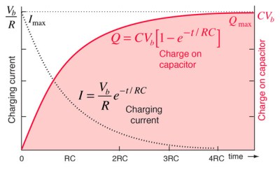
After some failed attempts, I had solved that by passing the buck converter output through a salvaged power MOSFET. A spare NodeMCU module provided pulse width modulated output that switched the MOSFET on for controlled periods of time to limit the charging current. That was fine, but a constant-voltage charger really isn’t the right way to load up a capacitor. Because the capacitor plates build up a voltage as it charges, the current output from a constant-voltage charger is high initially, but drops to a very low rate in the end.
To make something more like a constant-current charger, and lacking a sense resistor, I connected the output to the ADC pin on the NodeMCU. It measures the voltage across the supercapacitor, and as it increases during charging, the NodeMCU increases the amount of time the MOSFET allows current to pass. In other words it increases the duty cycle as the capacitor charges. Note that the firmware I was using supported integer math only, which is why I didn’t just divide by 1.6 in the code:
pwm.setup(1, 1000, 900)
pwm.start(1)

function set_charge_rate()
val = adc.read(0)
duty = 800 - (val/2 + val/9)
pwm.setduty(1, duty)
end

tmr.alarm(1, 3000, 1, function() set_charge_rate() end)
This worked much better, but the charge rate was still slower than it could be above around 2.1 volts. To speed it up a bit, I just increased the duty cycle to a fixed value above that point:
pwm.setup(1, 1000, 900)
pwm.start(1)

function set_charge_rate()
val = adc.read(0)
if val < 635 then duty = 800 - (val/2 + val/9) print (val) print (duty) pwm.setduty(1, duty) elseif val > 634 then
duty = 180
print (duty)
pwm.setduty(1, duty)

else
end
end

tmr.alarm(1, 3000, 1, function() set_charge_rate() end)
After that last modification, the charge rate was much better and the components involved would get hot, but not alarmingly so. I set the output of the DC-DC converter to 2.6 V, and was able to charge the capacitor past 2.5 V without issue.
Now that the charger was satisfactory, it was time to add electrodes. I had some large copper ring terminals, which were the right size for some steel bolts I had lying around. Crimping wire into these required quite a bit of hammering, but the connection was extremely solid. For cabling, I used three-phase power cable with all three wires attached together to make one thick cable.
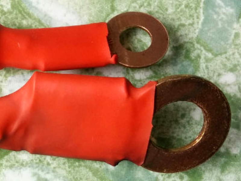 I bolted the ring terminals to the copper plates of the supercapacitor holder and to two short, thinner solid core wires that were the electrodes. While ugly, this gave the electrodes good mobility. It was pretty easy to apply them to metal plates and such. Finally, where there was exposed copper, I used heat shrink tubing as insulation.
So far, everything had gone pretty well, so I charged it up, grabbed a spare lithium cell and some tab wire, and gave it a try. When I applied the electrodes, a small spot on the tab wire got yellow-hot very fast without sparking. I quickly removed them… and the tab wire didn’t adhere at all. No matter how I tried, I couldn’t get it to weld in place, although it did heat up whatever material I touched the electrodes to rather well without any part of the device getting particularly hot itself. It feels like it just barely didn’t work, which was a bit frustrating. It did nicely obliterate the tab wire if left on too long though:
In hindsight, there are a few things I could have done better from the start. Most importantly, I should have used both capacitors to make a 5.4 V, 1500 F capacitor bank. Since I don’t know the internal resistance of the supercapacitor (I had incorrectly guessed around 30 mΩ), I should have erred on the side of pessimism. Looking at this working build that uses supercapacitors to weld copper, they had used four supercapacitors of similar size! So I charged both capacitors, sanded the electrodes clean, and hooked them up in series in a box for a quick test.
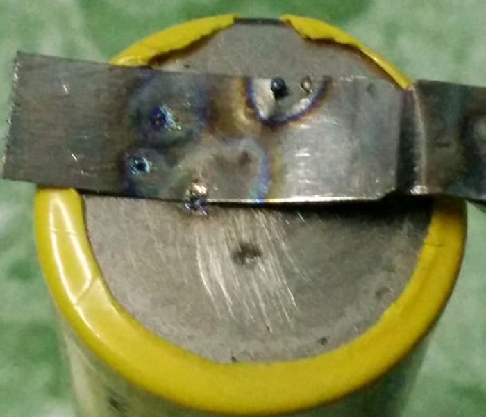
What a difference that made! When the electrodes touched the tab wire, they sparked lightly as expected rather than just heating the metal, and it welded into place. Certainly not the best weld, but with some practice I think it could be serviceable. (The actual welds are those spots on the left. The tab was damaged from previous attempts.)
 So while this works with a charge of 5.2 V, I suspect it would be better with a third capacitor at 7.8 V. A question remains though: why do some builds seem to work well with only a single supercapacitor? I suspect that these unbranded capacitors didn’t pass quality control, and were sold gray market. A higher than expected internal resistance or lower capacity than claimed are not out of the question and would certainly affect the performance of a spot welder. Lesson learned: for spot welders use genuine parts. I’ve half a mind to open it up, expecting to see a smaller capacitor inside along with a whole bunch of sand. That being said, for $4 these would have been fantastic as part of a trickle charge system for a solar-powered sensor.
Failing that, these questionable parts would make excellent ballast or a terrible casserole. Your project suggestions are welcome!
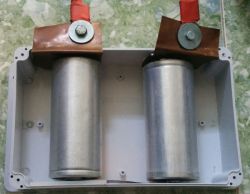
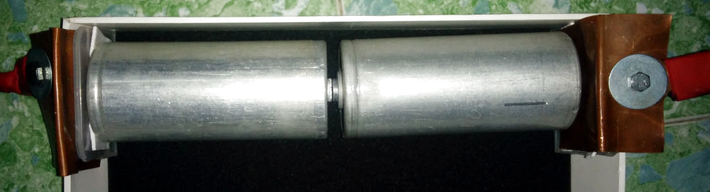
In any case, it was time to put it in a better box, make it portable, and attach a solar panel. That turned out to be refreshingly straightforward. I went and bought a larger weatherproof plastic box to enclose the supercapacitors. They’re arranged just as if they were large AA batteries.
I bought some slotted angled steel. This is pretty much my favorite construction material, it’s more or less scaled up Meccano. An interesting fact is that the existence of Meccano is what prevented a general patent for slotted angled steel, which allowed it to be emulated worldwide. I’ve seen buildings made from it.
I built a steel frame to fit a solar panel on top and contain all the parts. This is so it can be strapped to a motorbike or worn as a backpack using bungee cord — inspired by [Joe Kim]’s art for the first article. The solar panel is a 10 W, 18 V monocrystalline unit that I kept around to charge devices during long power outages that used to occur weekly (the power grid is much better now).
In sunlight, the charge time is limited more by the charge controller (in software) than the solar panel output. At the specified limit of 5 A, it just runs too hot. As a compromise, each capacitor has its own charge circuit, which can easily take 15 minutes to get from 1 V to a practical voltage.
Overall it works… but calling it amazingly practical would be quite a stretch. A more modest build using three or four smaller, branded supercapacitors would have likely worked better, charged faster, as well as being lighter, smaller, and cheaper… perhaps to the point of borderline commercial viability for people who need to weld battery tabs when the power is out. Or I could just give up portability and solar power altogether and use a microwave transformer to build the spot welder.


“Or I could just give up portability and solar power altogether and use a microwave transformer to build the spot welder.”
Before doing that.. if you wanted portable.. maybe something that plugs into a car cigarette lighter outlet to charge and can then be unplugged and carried away for use.
If you already have a car, why not use the battery directly? Even the relatively small ones have little trouble supplying 100s of amps for a short time…all you have to make is the switch that can do short pulses…
But I think Sean only has a scooter…
I used a car battery (back in 1993) to blast the shorts out of a laptop battery’s NiCad cells.
I was in a poorer barrio in Colombia at the time, so not much access to bench electronics…
Instead of a switch, I just quickly scratched one of the car’s battery posts.
Edit:
I just quickly scratched one of the car’s battery posts ^with one of the small wires I was using^.
What an idiot I am.
Sometimes you really wish there was an undo post button
Please do the humane thing and delete these two comments.
Absolutely not.
They are going to be preserved for posterity, and your future embarrassment of course :P
Congratulations Sean!
“Note that the firmware I was using supported integer math only, which is why I didn’t just divide by 1.6 in the code:”
Wait, are you talking about why you did (val/2 + val/9)? If you only have integer math, and you want to do float operations, don’t forget you can combine *multiplication* and division, and you’ll usually get a better result. Even better if you can find a nearby power-of-2 fraction.
In this case, dividing by 1.6 (assuming that’s exactly what you wanted) is the same thing as multiplying by 5 and downshifting 3 (1/1.6 = 10/16 = 5/8).
Except x/2 + x/9 is not equal to x/1.6. x/2 + x/8 is equal to x/1.6.
(Val * 5) >> 3
Yes, but the code says (val/2 + val/9). There’s nothing in the code that’s actually dividing by 1.6, which is why I wasn’t sure what he was talking about.
Even if you wanted (val/2 + val/9) you’d likely be better off doing (val * 11)/18 anyway unless there’s range issues or something. Of course given that it’s integer math you’d likely be better off finding something simpler and close anyway, as it’s not like you’re actually going to get precision.
That’s a good idea and I’ll try it next time!
The capacitor-based spot welder I made for myself used a hockey-puck SCR to switch the current into the electrodes _after_ setting them on the weld at the right pressure. Are people really doing this with no switch?
FWIW, I didn’t use super caps, I used old “computer grade” caps, about 140k uF and around 60v adjustable. Not only batteries, but also type-C thermocouples (tungsten!).
Of course I also have the horrible-fright version for less critical needs.
So your welder is monopulse? (as the SCR itself can’t go open state until the voltage drops)
p.s. 140k uF -> 140mF
the prefixes exist for a reason :D
Was “To recap” a pun or…?
It’s fairly standard usage, particularly in academic circles, and the context looks ok so probably not.
I totally missed that. My subconscious is probably trolling me again.