Typical power strips have their sockets tightly spaced. This makes it cumbersome to connect devices whose wall warts or power bricks are bulky — you end up losing an adjoining socket or two. And if the strip has a single power switch, you cannot turn off individual devices without unplugging them.
Planning to tackle both problems together, [Travis Hein] built himself some custom Dual SSR Controlled Socket Outlets for his workbench. He also decided to add remote switching ability so he could turn off individual sockets via a controller, Raspberry Pi, smartphone app or most ideally, a nice control panel on his desk consisting of a bank of switches.
The easiest solution for his problem would have been to just buy some off-the-shelf SSR or relay modules and wire them up inside his sockets. But he couldn’t find any with the features he wanted, and SSR’s were a little bit on the expensive side. Also, we wouldn’t have a project to write about – sometimes even the simple ones can show us a thing or two.
For starters, he walks us through a quick and simplified primer on figuring out thermal dissipation for the triacs which will be used on his boards. This is tricky since the devices are connected directly to utility voltage so he needs to take care of track clearances, mechanical separation as well as safety. However, for his first board prototypes, he did not add any heat sinking for the triacs, thereby limiting their use to low current loads. Since the SSR also needs to have a wide control voltage range, he describes how the two transistor constant-current input block works to limit opto-triac LED current over a range of 2 V to 30 V.
Before he moves on to his next prototype, [Travis] is looking for feedback to improve his design, make it safer, and figure out if it can pass safety protocols. Let him know via comments below.


Simplest way to do power metering is with something like a ATM90E32.
Check out sinewaving dimming. With sinewave dimming you use a pair of FETs to manipulate the AC wave form.
It will cost on the order of $25,000 to get UL approval. You can buy UL approved wifi controlled outlets from TP-Link for $30.
You can get it listed without it being UL approved. UL is just one of several companies that offer listing and testing services.
Curious what the practical rating is for inductive versus capacitive loads? Should it have any additional safeguards?
Is UL / NRTL listing/approval even required? I was under the impression that it’s optional — but a good idea.
The listing is not required, but no reputable store will carry your products without it. UL / NRTL listing enables your company to buy product liability insurance. So that if your product kills someone or burns their house down you won’t lose your company from the ensuing legal mess. Since the place that sold the product will also get sued, reputable stores require you to carry product liability insurance and you have to have a UL/NRTL listing before anyone will sell it to you. That’s why all of the uncertified junk is sold by Fulfilled-by-Amazon vendors and not Amazon itself. Amazon won’t carry it. When we had the hoverboard fires people tried to sue Amazon and learned that Amazon did not sell them the product, some tiny vendor with no insurance sold it. Amazon simply put a box in the post on behalf of the vendor and charged the vendor a fee. Then US customs got involved an stopped the import of any non-UL/ETL listed hoverboards.
A UL sticker on a device means little. I worked at a medical device manufacturer in Etobicoke, Toronto
Every time UL wanted to inspect the approved product, we would bring out and dust off 6 or 7 ‘queens’ (especially constructed units), change the serial number label, which had the alleged date of manufacture. These units would be placed on the ‘tested’ shelf.
A workstation would be cleaned off, and two units in mid assembly and necessary test equipment would be on display when the ‘Man from UL’ arrived.
He checked out the mid-assembly units, then he selected 2-3 units from the ‘tested’ shelf for his testing. After completing his inspection, and all as well, he was then invited out for luncheon and off he went.
The ‘queens’ were carefully stored away for the next ‘inspection’ and life carried on.
As an owner of a business, I would fire you instantly for doing that. I am paying UL to ensure that my devices are safe. If an unsafe unit injures someone the resulting legal could destroy the entire company.
I assume it was the owner of the business that wanted it to be done like that.
More likely some middle manager trying to earn a bonus by cheating the system.
Came from the top. Makes it hard to trust any standards like UL or CSA.
The fault if not with UL or CSA, the fault is with your company for deceiving the UL/CSA inspectors. Can’t you see that the purpose of the UL inspections was to keep substandard components out of the supply chain? And in a medical device if one those substandard components failed it could result in the death of a patient? This is right up there with making fake parts to go into jet engines, where if they fail lots of people die.
Cheating UL like that, especially on medical devices, is likely a criminal offense in the US. This is similar to the VW emissions testing scandal. For example selling a falsely certified device to a Medicare recipient would make it fraud at a Federal level which is a criminal offense.
The company I worked at, we checked the calibration of every UL test device every shift with instruments of current NIST traceable testing. QA inspectors were testing product throughout the shift down to every letter of the serial numbers. A bad run on a shift could easily run the price of a new house, if it made it to the customer could be countless millions of dollars. UL and auditors were our friends, because quality kept orders coming in.
This is fairly similar to my Toast-R-Reflow power board.
https://hackaday.io/project/3908-toast-r-reflow
Do you know how long it took me to work out that SSR = Solid State Relay? I’m not a smart boy, acronyms hardly work for me, but, not one sentence mentioned it, I looked it up, google doesn’t even give reference, only after I clicked into the github link it click to me.. oh look, its also a tag.
Tagged constant current source, MOC3063M, power brick, relay, solid state relay, ssr, TRIAC, wall wart?
The article should define terms used within the article at least once, precisely to prevent confusion.
As well as those ACRONYMs placed by commenters!
ACRONYM: Abbreviated Coded Rendition Of Nomenclature Yielding Meaning
I agree, it would be generally helpful to do so and it’s somewhat typically done here. SSR is bordering on a standard enough term in this space that the author probably didn’t feel the need to do so here? At least it was defined in the tags section though.
Ok but where’s the limit ? The article also uses the LED acronym without defining it…
That’s a pretty standard acronym. I didn’t think it was hard at all.
Should every component mention in every article be a link to it’s “All About Circuits” page? Really?
I agree with ajrgale. I was confused and I had even shopped SSRs just a few months ago. Forgot the term.
I like the use of the constant current source for the opto led makes for good versatility on the driver side –
Heat dissipation would be a problem for higher powers but for small bench devices it’ll be cool. An alternative to get a higher power rating would be to use isolated tab to220 packages and fix them to the metal housing and make sure the housing is earthed just in case. I drive a 2400W hot water heater off a single triac with a fairly minimal heat sinking.
Hi Saabman, please can you elaborate a little more on that? I’m going to do a couple of those for my diy homebrew machine and altought I already did some sucessfull SSRs in the past, none of them were for power control, they just turned on/off on the zero crossing (MOC3040 IIRC) I would like to not caramelize my wort. Thanks. (sorry for my english)
“caramelize my wort. Thanks. (sorry for my english)”
I first read that to mean “cannibalize my work”
B^)
Here you go https://hackaday.io/project/11499-electric-water-heater-controler
As mentioned above I used the Isolated tab version of the same TRIAC. No need for snubbers due to their high commutation performance – just drive the load directly. :-)
Ive just finished the circuit and PCB design for another project again driving 240V loads. Ill upload the files in the next couple of days https://hackaday.io/project/28205-hydroponics-control
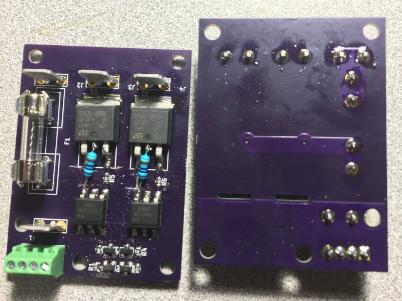
As I was curious to the components used I cloned his github repro.
First: It is nice to see an overview on github for the project.
Too many projects on github only have less than a handfull of text there.
The overall design is a current source/sink for the led of a MOC3063, which triggers a beefy triac.
All that times 2 and with a single 10A fuse.
Bad thing about this project is that though he blabs about thermall stuff, the PCB area does not have any extension for thermal dissipation for the triac, and this way the circuit is not safe to use with 10A fuses.
But I have to admit that those steel boxes will let the smoke escape through their holes, but not much fire or the other really nasty stuff.
Main complaint was the cost of pre-fabricated solid state relay’s, and he links to an USD 37 part on digikey.
I have liked the S201s01 from Shap.
Nice compact isolated housing and can switch a reasonable amount of current.
Unfortunately obsolete according to digikey.
I did not look for a replacement on those 600+ pages on digikey with solid state relay’s.
But if you are “price concious” you do not go to digikey anyway.
Ali has plenty of them for about EUR1.70 each.
https://www.aliexpress.com/wholesale?SearchText=s202s01
S202S01 can also be easily mounted / screwed to the side of this metal box for some extra cooling and would seem an excellent choise for mounting in such a box.
(Note: These come in different versions, with and without zero crossing).
Overall:
I’m impressed with the amount of documentation for this project, but not with much else.
There is just NO WAY I would trust a SSR pretending to be a S202S01 for 1.70 EUR delivered !
If safety is a priority, I would not be buying from “AliExpress”.
If you are working with mains voltage I would not trust anything from Ali that sells for 1/t0 the price compared to Mouser or Digikey. Go watch the youtube videos by BigCive on ebay SSR’s.
It’s quite clear those SSR’s are not what the seller claims them to be. If you are willing to accept dodgy Chinese made gear hooked to your mains, you are asking for trouble.
This design looks quite nice, but as always there is some space for improvements. Some things that came to my mind:
First, I’d separate the power ground and the low voltage ground completely; that way the noise sensitivity increases if e.g. long cables are used and the ground potential between the solid state relay and the control is different. Reinforced insulation is then needed over the optoisolator, but that should not be an issue.
Second, I’d add an RC snubber over the triacs to protect them from line transients, decrease radiated emissions during turn-off and protect the triac from spurious turn-on especially if the load is inductive. It may be difficult to dimension the RC snubber correctly, but there is lots of literature available on that subject. At least leave space for them in the layout should the snubber be needed in the future.
A minor things about the layout: currently ground is poured under the optoisolator, I would keep the copper completely out from below the optos to increase the creepage/clearance. The current design might have enough clearance already, but a little extra never hurts as there is no need to pour it below the optos. Also one might want to pour the high voltage side with the “always hot” potential to increase the heat dissipation capability. Just keep enough clearance to the switched nodes (functional isolation). With D2PAKs the PCB is the most important heat sink so it is recommended to have as much copper area as possible, and also use vias to stitch them together.
The snubbers arn’t really needed with those TRIACS with high commutation performance and using zero crossing detection drivers the turn on and off is at 0V so switching noise is next to nothing
The above is an important comment. The MOC3063 will typically inhibit turn-on/turn-off above 5V and certainly always above 20V. This can truly reduce in-rush stress in many types of power circuits as well not exciting big turn-on/turn-off spikes back into the mains.
Nice little basic circuit!
However, I would have liked to see some input filtering, surge protection, capacitive/inductive load handeling, snubber, etc…
I hope Travis gets his hands on some more money soon.
If alone so he can use a nicer enclosure, or maybe paint it so it looks nicer, but hey, money is always good to have in general too.
I especially liked the warnings on github – the only thing missing was the observation it was going to hurt the whole time you’re dying :-)