WiFive55: More Than A Smart 555 Replacement

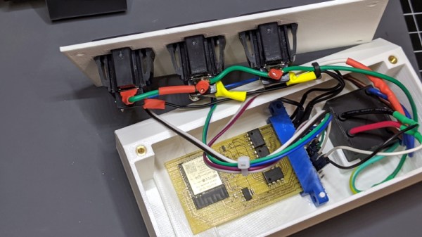
“You could’ve done that with a 555 timer.” But what if all you have on hand is an ESP8266? [TechColab] needed to control a solenoid valve with a short pulse via a solid-state relay (SSR) but found that the trusty 555 timer was tricky to set properly. Additionally, they wanted to add features, such as fixed pulse length, that were difficult to implement—even with multiple timers. Still wanting to keep things cheap and accessible, [TechColab] has created the WiFive55, a 555 replacement based on the ESP-01 ESP8266 board.

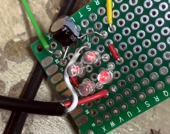
[TechColab] began by investigating existing ESP-01 solid-state relay boards but found that many of them momentarily enable the output on startup—a risk [TechColab] deemed unacceptable. This was resolved in the WiFive55 by adding an RC filter to the SSR output, eliminating the output glitches at the cost of slowing switching time to around 20 ms—an acceptable trade for many SSR applications.

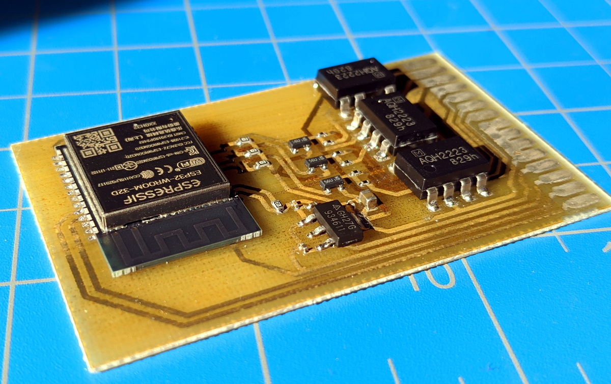
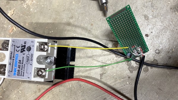
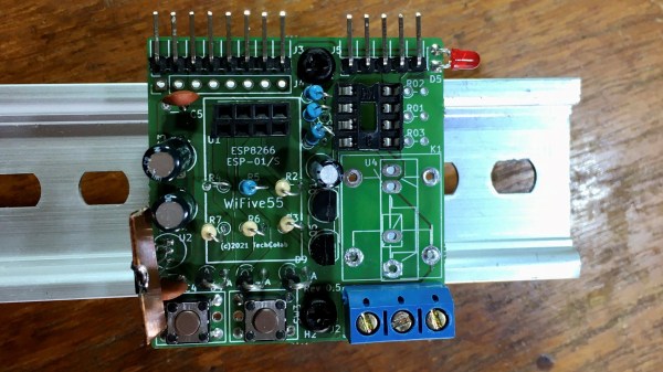
Since they were going to design a new PCB to support this improved ESP-01 SSR controller, [TechColab] decided to go all-out. To support loads of widely varying sizes, the PCB supports an optoisolator that switches up to 1 A, a MOSFET that switches up to 2 A, and an on-board relay or SSR that can switch up to 3 A. For heavy loads, it includes connections for an off-board SSR, which allow it to switch whatever current the SSR can handle (easily over 50 A). Because the ESP-01 is slightly more capable than the 555, the WiFive55 supports control via WiFi, GPIO, serial, and push-button. Keeping with the WiFive55’s original role as a 555 replacement, it even includes a header exposing a 555-like trigger and output interface!

We always like seeing inexpensive boards like the ESP-01 being used to their full potential, and we can’t wait to see what software [TechColab] cooks up for this! If you’re interested in getting started with the ESP-01, you might consider starting with this guide to blinking an LED over WiFi.

Touch Screen Reflow Oven Pulls Out All The Stops

We’ve seen plenty of simple reflow ovens, and there’s an excellent chance that some of the people reading these words have even thrown their own together. A minimal example isn’t much more than a old toaster oven, a Solid State Relay (SSR), a thermocouple, and a microcontroller to get them all talking. But if you’re like [Mangy_Dog] and willing to put in a bit more effort, the final result can be a capable piece of equipment that will be the envy of the hackerspace.

This build started as most do, with a search for a used toaster oven. But in the end he actually found a German model cheap enough that he could buy it new without going over budget for the project. Though he soon found out why: when it arrived, the so-called “pizza oven” was far smaller than he’d imagined. Luckily, it ended up being the perfect size for PCBs.

Unfortunately, the heating elements weren’t quite where he wanted them. Even after wrapping the heating chamber with ceramic insulation, a feature that was likely left off the original oven to cut costs, he says the temperature would only rise about 1 degree per second. So he added an additional halogen heating element at the top of the oven which pushed that rate up to 6 degrees per second.

Control is provided by an Arduino Pro Mini and a touch screen display with some very slick graphics. There’s the expected thermocouple to detect the current temperature, but while the earlier versions of the electronics used the aforementioned SSR to control the heating elements, [Mangy_Dog] eventually replaced it with a dimmer module rated for 4000 watts. After coming up with a circuit that allowed him to control the dimmer with the Arduino, this module gave for much finer control over the chamber temperature. Plus it apparently kept all the lights in his house from flickering when the elements kicked in at 100%, which was a nice bonus.

This isn’t the first time we’ve seen somebody shoehorn an LCD into an off-the-shelf toaster oven, but it’s certainly one of the most polished examples to ever come our way. When even commercially available units need some hacking to reach feature parity with DIY versions, building your own reflow oven still seems like the way to go in 2020.

Continue reading “Touch Screen Reflow Oven Pulls Out All The Stops”

Building An ESP32 Smart Power Strip From Scratch

Surely the most straightforward way of creating a smart power strip would be to take an existing model and hack in some relays that you could fire with a WiFi-enabled microcontroller. But where’s the fun in that? Instead of repurposing a commercial power strip for his recent project, [Md Raz] decided to just build the whole thing himself.

The project started with a 3D printed enclosure that could hold the electronics and three panel mount sockets. The use of heat-set inserts makes it a bit more robust for future upgrade work, but otherwise it’s a fairly simple rectangular design. Nobody ever said a power strip had to be pretty, right? In addition to the panel mount sockets, there’s also a AC-DC converter to step mains voltage down to 5 VDC for the ESP32.

In addition to the microcontroller, the custom PCB in the power strip holds a trio of MOSFETs connected to AQH2223 solid state relay (SSR) chips. Once the ESP32 toggles the line attached to each MOSFET, the indicator LED above the outlet goes on and the appropriate SSR is thrown to turn on the power. With a simple web interface running on the microcontroller, all three outlets can be independently controlled from any device with a web browser.

If you’d like to limit your interaction with mains voltages, then we’ve seen some projects that commandeer the low-voltage side of a commercial smart power strip. But remember, putting a Raspberry Pi inside of a power strip might seem suspicious to some folks.

Vacuum Dust Collection With Self-Powered Relays

Like many people with multiple woodworking tools, [Will Stone] wanted to create a centralized dust collection system. But he quickly found that the devil was in the details, as he struggled to find an economic way to automatically kick on the vacuum when one of the tools started up. His final solution might be one of the most elegant, and surely the cheapest, we’ve ever come across.

As with other DIY systems we’ve seen over the years, [Will] is using a simple inductive current sensor to detect when AC power is being drawn by one of his tools. But where the similarity stops is that there’s nothing so pedestrian as a microcontroller reading the output of the sensor. He realized that when the coils in the sensor were energized they were putting out about 7 volts AC, which should be more than enough to trigger a relay.

So he threw together a rectifier circuit on a piece of perfboard, using four LEDs in true hacker style. With the addition of a capacitor to smooth out the voltage, this little circuit is able to trip the 40 amp solid state relay controlling power to the vacuum using nothing more than the energy harvested from the sensor’s coil.

Using a current sensor is great when the tools are close enough to all be plugged into the same line, but that doesn’t help the folks with cordless tools or supersized shops. In that case, you might need to look into a sound-activated system.

Solid State Relay Simulation, Explained

[SaltyPuglord] needed a solid state relay for a project. We’d have just bought one, but he decided to design his own in LTSpice. Along the way he made the video below, which is pretty informative and a good example of a non-trivial design in LTSpice.

MOSFETs have made designs like this a lot easier, to the extent that it should be as easy as putting a pair of beefy fets in-line with the AC source and load. However, that has a few ramifications that [Salty] covers in the video.

The biggest concern comes in isolating the DC supply from ground. He used a transformer which is tricky to simulate in LTSpice. Beyond that the design of the power supply is quite simple, and as he mentions in the video, you don’t really need this complex of a regulator just to feed the gates of the MOSFETs.

Continue reading “Solid State Relay Simulation, Explained”

Building A Sound Activated Shop Fan With Arduino

Whether you’re using a soldering iron or a table saw, ventilation in the shop is important. Which is why [Atomic Dairy] built a monster air cleaner called the Fanboy that looks like it should be mounted under the wing of an F-15. Realizing a simple switch on the wall wouldn’t do this potent air mover justice, they decided to build a sound activated controller for it.

It’s certainly an elegant idea. The sound created once they kick on their woodworking tools would be difficult to miss by even the most rudimentary of sound-detection hardware. At the most basic level, all they needed was a way for an Arduino to throw a relay once the noise level in the room reached a specific threshold.

Of course it ended up getting a bit more complicated than that, as tends to happen with these kinds of projects. For one, the sound doesn’t directly control the solid state relay used in the fan controller. When the microphone equipped Arduino detects enough noise, it will start a timer that keeps the fan running for two hours. If the tool keeps running, then more time gets added to the clock. This ensures that the air in the room is well circulated even after the cutting and sanding is done.

[Atomic Dairy] also added a few additional features so they could have more direct control over the fan. There’s a button to manually add more time to the clock, and another button to shut it down. There’s even support for a little wireless remote control, so the fan can be operated without having to walk over to the control panel.

We’ve seen some impressive air circulation and dust collection systems over the years, but finding a way to elegantly switch them on and off has always been a problem given the wide array of tools that could be in use at any given time. Sound activation isn’t a perfect solution, but it’s certainly one we’d consider for our own shop.

Continue reading “Building A Sound Activated Shop Fan With Arduino”

Fail Of The Week: Solid State Relay Fails Spectacularly

A lot of times these days, it seems like we hackers are a little like kids in a candy store. With so many cool devices available for pennies at the click of a mouse, it’s temptingly easy to order first and ask questions about quality later. Most of the time that works out just fine, with the main risk of sourcing a dodgy component being a ruined afternoon of hacking when a part fails.

The stakes are much higher when you’re connecting your project to the house mains, though, as [Mattias Wandel] recently learned when the solid-state relay controlling his water heater failed, with nearly tragic results. With aplomb that defies the fact that he just discovered that he nearly burned his house down, [Mattias] tours the scene of the crime and delivers a postmortem of the victim, a Fotek SSR-25DA. It appears that he mounted it well and gave it a decent heatsink, but the thing immolated itself just the same. The only remnant of the relay’s PCB left intact was the triac mounted to the rear plate. [Mattias] suspects the PCB traces heated up when he returned from vacation and the water heater it was controlling came on; with a tank full of cold water, both elements were needed and enough current was drawn to melt the solder build-up on the high-voltage traces. With the solder gone, the traces cooked off, and the rest is history. It’s a scary scenario that’s worth looking at if you’ve got any SSRs controlling loads anywhere near their rated limit.

The morals of the story: buy quality components and test them if possible; when in doubt, derate; and make sure a flaming component can’t light anything else on fire. And you’ll want to review the basics of fire protection while you’re at it.

Continue reading “Fail Of The Week: Solid State Relay Fails Spectacularly”